Constant-current current-limiting inverter

An inverter and current limiting technology, applied in the direction of converting AC power input to DC power output, converting irreversible DC power input into AC power output, and output power conversion devices, etc., can solve the problem of affecting the normal output of current and realize Problems such as complex process and complex control process, to achieve the effect of constant current limiting output, optimized control mode, and short development cycle

Active Publication Date: 2014-12-24
NEW FOCUS LIGHTING & POWER TECH
View PDF9 Cites 2 Cited by
  • Summary
  • Abstract
  • Description
  • Claims
  • Application Information

AI Technical Summary

Problems solved by technology

[0002] The inverter is a device that converts DC power into AC power. According to the control method, the existing inverters can be divided into open-loop control inverters based on 8-bit MCU, and complex multi-closed-loop control inverters based on DSP. There are two kinds of inverters; DSP multi-change control inverter has complex control process, stable output, and strong start-up ability, but its implementation process is complicated, the development cycle is long, and the cost is relatively high; 8-bit MCU is used as the inverter of the core control IC. The inverter is simple to implement and low in cost, but when it is used in high-power electrical appliances, if it needs to output a large current normally, the short-circuit protection and overload protection of the inverter will be severely degraded. short-circuit protection, overload protection and other performance of the transformer, it will seriously affect the normal output of current

Method used


Image

  • Constant-current current-limiting inverter

Examples


Embodiment Construction

[0033] The present invention will be further described below with reference to the accompanying drawings and specific embodiments, but it is not intended to limit the present invention.

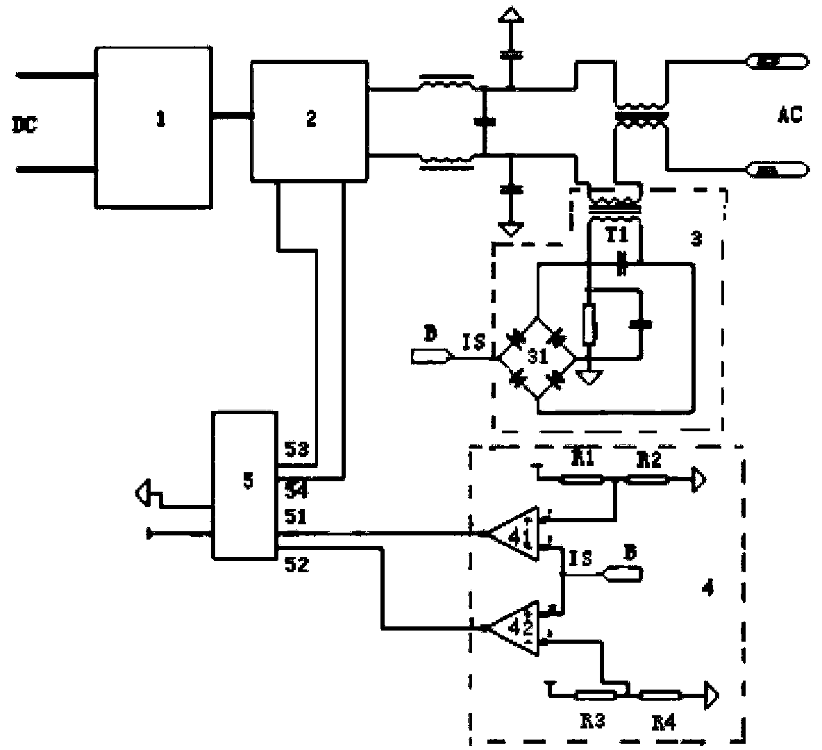
[0034] like figure 1 Shown is a constant-current current-limiting inverter for converting direct current into alternating current, including:

[0035] The booster 1 is used to increase the voltage of the direct current;

[0036] The H-bridge circuit 2 is provided with a rectifying and filtering device, and is used to convert the DC power output by the booster into AC power;

[0037] The sampling module 3 is used to sample the current of the alternating current output by the H-bridge circuit 2, and rectify it into a voltage value signal corresponding to the voltage output by the H-bridge circuit 2 and with a constant direction;

[0038] The comparison module 4 is set with the highest threshold value and the lowest threshold value, and the comparison module 4 judges whether the voltage output...


PUM


Abstract

The invention discloses a constant-current current-limiting inverter. The constant-current current-limiting inverter comprises a voltage booster, an H-bridge circuit, a sampling module, a comparison module and an MCU. The voltage booster is used for increasing the voltage of direct current. The H-bridge circuit is provided with a rectifier filter device and used for converting the direct current output by the voltage booster into alternating current. The sampling module is used for conducting current sampling on the alternating current output by the H-bridge circuit and rectifying the alternating current into a voltage value signal IS which corresponds to voltage of the output end of the H-bridge circuit and is constant in direction. A maximum threshold value and a minimum threshold value are set for the comparison module, and the comparison module judges whether the voltage output by the H-bridge circuit is between the maximum threshold value and the minimum threshold value according to the voltage value signal IS. The MCU controls the H-bridge circuit to be on or off according to output of the comparison module. The constant-current current-limiting inverter has the advantages that the situation that starting power of the H-bridge circuit is affected due to changes in performance of short-circuit protection and overload protection is avoided, the structure is simple, the cost is low, the development cycle is short, the current output is stable, and the constant-current current-limiting inverter can be applied to high-power electrical appliances.

Description

technical field [0001] The invention relates to a power converter, in particular to a constant-current current-limiting inverter. Background technique [0002] The inverter is a device that converts DC power into AC power. According to the control method, the existing inverters can be divided into open-loop control inverters based on 8-bit MCU, and complex multi-closed-loop control inverters based on DSP. There are two types of inverters; DSP multi-change control type inverter, the control process is complex, the output is stable, and the startup ability is strong, but its implementation process is complex, the development cycle is long, and the cost is relatively high; 8-bit MCU is used as the inverse of the core control IC. The inverter is simple to implement and has low cost, but when it is used in high-power electrical appliances, if a large current is to be output normally, the short-circuit protection and overload protection of the inverter will be seriously degraded. ...

Claims


Application Information

Patent Timeline
Patent Type & Authority Applications(China)
IPC IPC(8): H02M7/44H02M7/5387H02H7/122
Inventor 洪伟弼徐斌
Owner NEW FOCUS LIGHTING & POWER TECH
Why Eureka
Try Eureka