High temperature resistant mechanical seal device

A mechanical seal device, high temperature resistant technology, applied in the direction of engine seals, mechanical equipment, engine components, etc., can solve the problems of auxiliary seal failure, limited effect, seal performance impact of seal rings, etc., to reduce mechanical deformation and thermal deformation. , Improve efficiency and service life, prevent seal leakage

Active Publication Date: 2016-04-06
SHANGHAI LEHE FLUID MACHINERY
View PDF8 Cites 0 Cited by
  • Summary
  • Abstract
  • Description
  • Claims
  • Application Information

AI Technical Summary

Problems solved by technology

[0002] At present, there are many types of mechanical seals used for rotating shafts, and the models are different, but the overall structure is usually composed of static ring components and moving ring components. The current mechanical seal devices have the following defects: 1. Conventional products are in the state of overheating in the sealing chamber. , it is easy to cause the deformation of the shaft sleeve, which will cause the frictional engagement between the relatively moving components with relatively small gaps including the diversion component and the labyrinth seal, which will seriously endanger the life of the mechanical seal and the safety of the equipment.
The thermal expansion of the mechanical seal sleeve can easily lead to the failure of the auxiliary seal inside the sleeve; 2. The conventional throttling ring and labyrinth seal have limited effect during operation due to the large seal gap; 3. The flushing water of the conventional mechanical seal is directly sent from the cavity If the side enters the seal, it should be because the flushing water pressure is concentrated and the flushing point is relatively single, so the flushing effect is not ideal, and even the sealing performance is affected by the uneven heating of the sealing ring

Method used


Image

  • High temperature resistant mechanical seal device
  • High temperature resistant mechanical seal device
  • High temperature resistant mechanical seal device

Examples


Embodiment 1

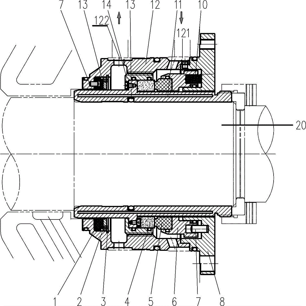
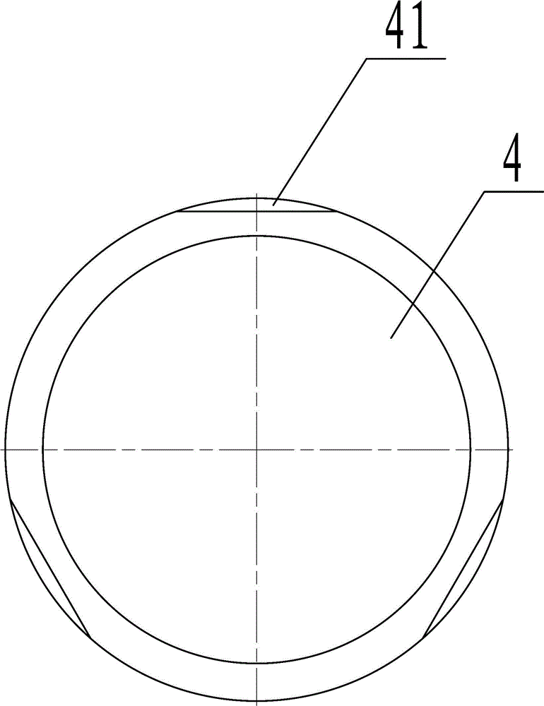
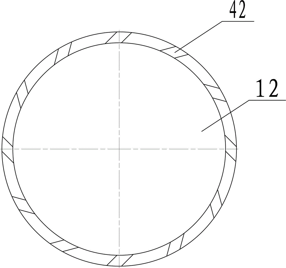
[0037] A high-temperature-resistant mechanical seal device, including a self-centering throttle ring 1, a pressure plate 2, a snap ring 3, a moving ring 4, a static ring 5, a static ring seat 6, a cylindrical pin 7, a gland 8, a compression spring 10, and a vacuum Shaft sleeve 11, outer flow guide sleeve 12, O-ring 13, inner flow guide sleeve 14 and rotating shaft 20, such as Figure 1 ~ Figure 3 As shown, the specific structure is:

[0038] The vacuum bushing 11 is a hollow structure, and the inner cavity of the vacuum bushing 11 is in a high vacuum state not higher than 0.01KPa. Ring 13, the outer surface of the vacuum bushing 11 is provided with an annular step;

[0039]The inner diversion sleeve 14 is a cylindrical shape with the bottom surface closed and one end open. The inner diversion sleeve 14 is sleeved on the vacuum bushing 11 through the through hole opened on the bottom surface, and the inner diversion sleeve 14 is fixed on the annular step of the vacuum bushing ...

Embodiment 2

[0058] A high-temperature-resistant mechanical seal device, including a self-centering throttle ring 1, a pressure plate 2, a snap ring 3, a moving ring 4, a static ring 5, a static ring seat 6, a cylindrical pin 7, a gland 8, a compression spring 10, and a vacuum Shaft sleeve 11, outer flow guide sleeve 12, O-ring 13, inner flow guide sleeve 14, O-ring 13 and rotating shaft 20, also includes positioning block 9, such as Figure 4 As shown, the specific structure is: one end of the positioning block 9 is sleeved in the positioning groove on the outer wall of the vacuum bushing 11, and the inner end surface of the positioning block 9 is detachably fixed to the flange chassis of the gland 8. Other structures are all the same as in Embodiment 1.

[0059] When this embodiment is in use, when it is not running, use the positioning block 9 to keep the mutual position between the gland 8 and the vacuum bushing 11 fixed, so that the positions of the remaining parts are kept fixed, and...


PUM


Abstract

The invention relates to the field of sealing devices for fluid medium conveying pipelines, in particular to a high-temperature-resistant mechanical sealing device. The high-temperature-resistant mechanical sealing device comprises a movable ring (4), a static ring (5) and a revolving shaft (20), and is characterized by further comprising a vacuum shaft sleeve (11) and an O-shaped ring (13), wherein the inner cavity of the vacuum shaft sleeve (11) is in a high-vacuum state; the vacuum shaft sleeve (11) is fixed on the revolving shaft (20) in a sleeving manner; the movable ring (4) is fixed on the vacuum shaft sleeve (11) in the sleeving manner; the static ring is rotationally arranged on the vacuum shaft sleeve (11) in the sleeving manner; the static ring (5) and the movable ring (4) are jointed together and rotate relatively; the O-shaped ring (13) is lined between the vacuum shaft sleeve (11) and the revolving shaft (20). The high-temperature-resistant mechanical sealing device has high sealing performance, low medium leakage, long running time and long service life.

Description

technical field [0001] The invention relates to the field of sealing devices for fluid medium delivery pipelines, in particular to a high temperature resistant mechanical sealing device. Background technique [0002] At present, there are many types of mechanical seals used for rotating shafts, and the models are different, but the overall structure is usually composed of static ring components and moving ring components. The current mechanical seal devices have the following defects: 1. Conventional products are in the state of overheating in the sealing chamber. , It is easy to cause the deformation of the shaft sleeve, which will cause the friction and bite between the relatively moving components with relatively small gaps including the diversion component and the labyrinth seal, which will seriously endanger the life of the mechanical seal and the safety of the equipment. The thermal expansion of the mechanical seal sleeve can easily lead to the failure of the auxiliary...

Claims


Application Information

Patent Timeline
Patent Type & Authority Patents(China)
IPC IPC(8): F16J15/34
CPCF16J15/34F16J15/3404
Inventor 夏立王晓
Owner SHANGHAI LEHE FLUID MACHINERY
Why Eureka
Try Eureka