A transfer device and a vacuum interrupter aging device using the transfer device

A technology of vacuum interrupter and transfer device, applied in high-voltage air circuit breakers, electrical components, electrical switches, etc., can solve the problems of difficult to guarantee quality consistency, insufficient utilization efficiency and high labor intensity

A technology of vacuum interrupter and transfer device, applied in high-voltage air circuit breakers, electrical components, electrical switches, etc., can solve the problems of difficult to guarantee quality consistency, insufficient utilization efficiency and high labor intensity

CN104576123BActive Publication Date: 2016-08-17TIANJIN PINGGAO INTELLIGENT ELECTRIC

Image

  • A transfer device and a vacuum interrupter aging device using the transfer device
  • A transfer device and a vacuum interrupter aging device using the transfer device
  • A transfer device and a vacuum interrupter aging device using the transfer device

Examples


Embodiment Construction

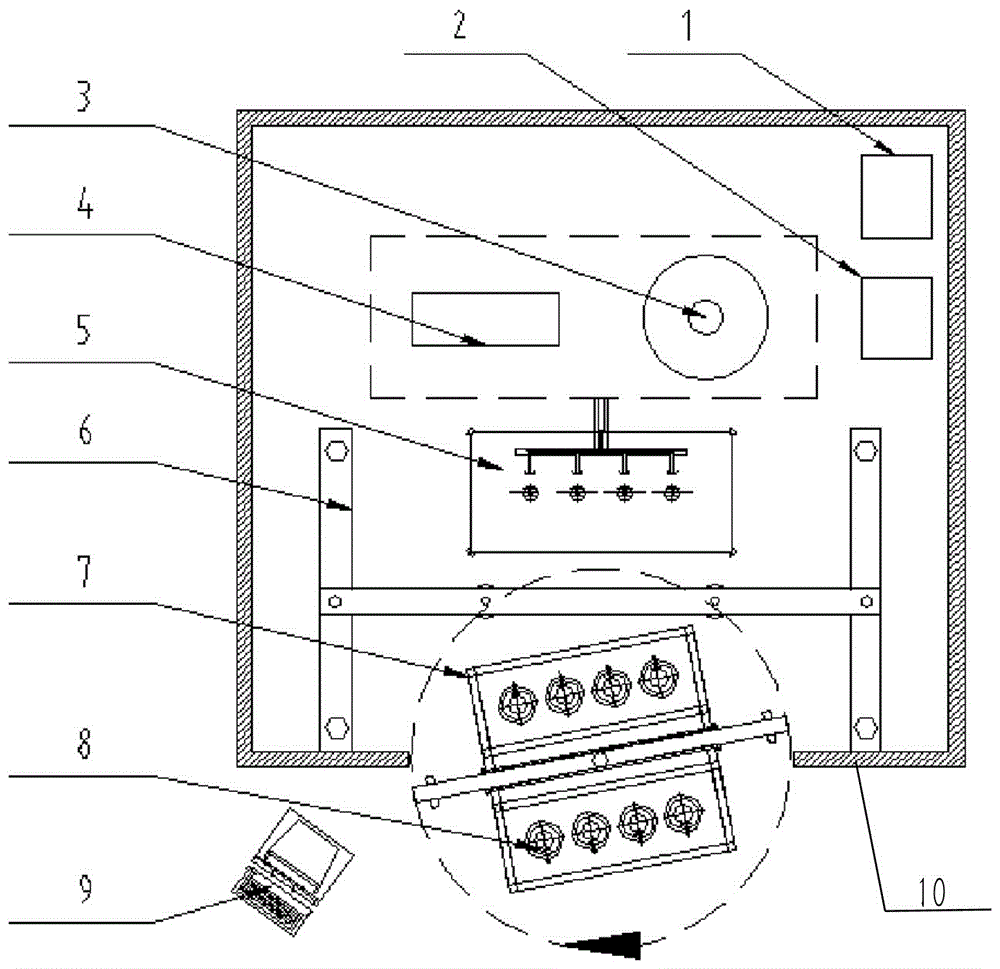
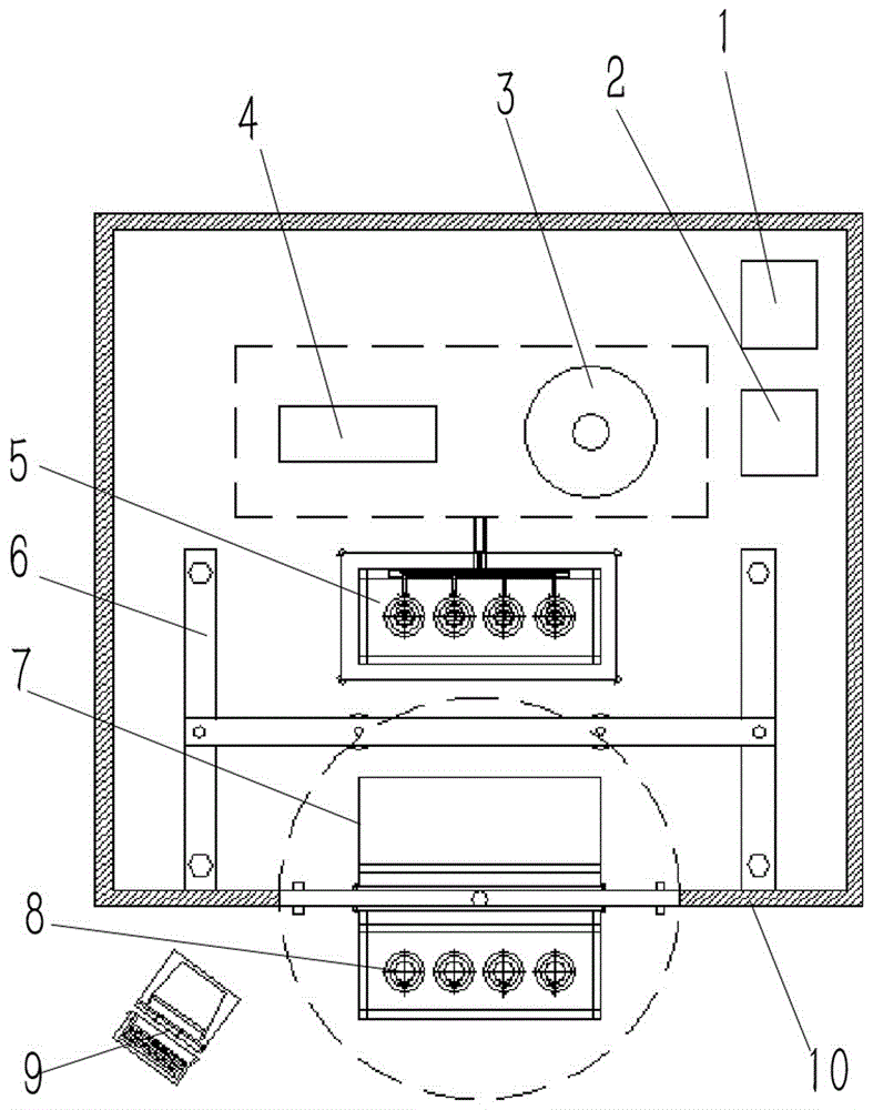
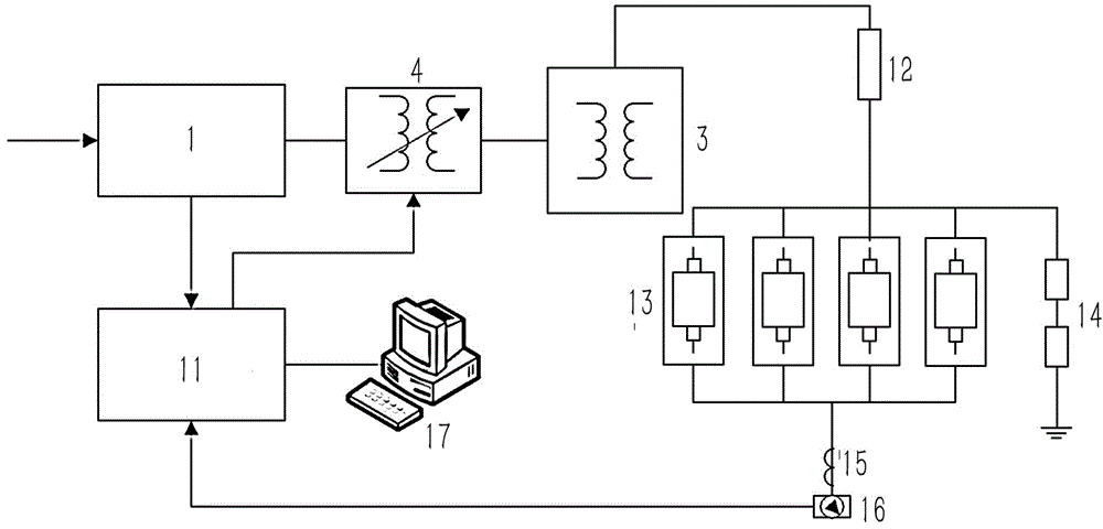
[0024] Embodiment of vacuum interrupter aging device in the present invention: as Figure 1 to Figure 7 As shown, the aging device is an automatic voltage aging device for vacuum interrupters used in the field of high-voltage switch processing and testing. It is mainly used to apply high voltage to various specifications of vacuum interrupters for aging processing to remove parts. Gas and impurity particles within a certain thickness on the surface eliminate microscopic burrs, refine grains, and improve the ultimate withstand voltage level of the interrupter.

[0025] The aging device is mainly composed of an aging lead room 10, a switch cabinet 1, a control cabinet 2, a transformer 3, a voltage regulator 4, an aging table 5, a shifting device 6, a loading device 7 and a monitoring table 9, wherein the switch Cabinet 1, control cabinet 2, transformer 3, voltage regulator 4, aging table 5 and shifting device 6 are all located in the aging lead room 10, and the transfer device 7...


PUM


Abstract

The invention discloses a load shifting device and a vacuum arc-extinguishing chamber aging device using the load shifting device. A load shifting port is formed in the wall of an aging lead room; the load shifting device which consists of a fixed seat, a support seat and a bearing unit is assembled in the load shifting port; a shifting device which is used for shifting the bearing unit with an arc-extinguishing chambers to be detected between an aging platform and the support seat is assembled in the aging lead room. During the use, the arc-extinguishing chambers to be detected shifts indoors and the detected arc-extinguishing chambers shift outdoors through the rotation of the support seat in the load shifting device on the fixed seat; after the arc-extinguishing chambers to be detected shift indoors, the load shifting port of the aging lead room is blocked by the support seat to prevent the harmful rays generated in the aging process from escaping, so that the automatic loading of the arc-extinguishing chamber aging operation is realized when the radiation resistance in the aging process is ensured and then the arc-extinguishing chamber aging efficiency is accelerated.

Description

technical field [0001] The invention relates to a transfer device and a vacuum interrupter aging device using the transfer device. Background technique [0002] At present, the voltage aging in the process of vacuum interrupter refers to the way of applying high voltage to the interrupter to cause strong spark discharge between the internal contacts and between the contacts and the shielding cover. With the help of such spark discharge to eliminate high beta emission points on internal parts. However, there are two problems in the voltage burn-in devices currently used by arc extinguishing chamber manufacturers: first, the adjustment of the burn-in voltage in the burn-in process needs to be determined by the operator according to the observed spark discharge phenomenon, which is affected by human factors. The interference is large, and the quality consistency is difficult to guarantee; second, because a large amount of X-rays harmful to the human body will be generated duri...

Claims


Application Information

Patent Timeline
17 Aug 2016
Publication
CN104576123B
IPC
H01H11/00; H01H33/664
CPC
H01H11/00; H01H33/664
Inventors
ηŽ‹ζ™“η΄; ηŽ‹δΌšε‹