Touch control panel and liquid crystal display device

A technology of a liquid crystal display device and a touch panel, which is applied in the fields of optics, instruments, and electrical digital data processing, etc., and can solve the problems of different display brightness and unstable voltage of the conductive network unit 30, and achieve the elimination of brightness differences and reduction of voltage differences. small effect

Active Publication Date: 2015-07-29
XIAMEN TIANMA MICRO ELECTRONICS +1
View PDF6 Cites 10 Cited by
  • Summary
  • Abstract
  • Description
  • Claims
  • Application Information

AI Technical Summary

Problems solved by technology

[0004] However, due to the coupling interference between the touch electrode 20 and the conductive network unit 30, the voltage on the conductive network unit 30 is unstable, and then the display brightness of the area corresponding to the touch electrode 20 and the area corresponding to the conductive network unit 30 are different when the screen is displayed. It is easy to reveal the outline shadow of the conductive network unit 30 in the picture, especially in the flickering picture, the outline shadow of the conductive network unit 30 is particularly obvious

Method used


Image

  • Touch control panel and liquid crystal display device
  • Touch control panel and liquid crystal display device
  • Touch control panel and liquid crystal display device

Examples


Embodiment Construction

[0021] In order to make the technical problems solved by the present invention, the technical solutions adopted and the technical effects achieved clearer, the technical solutions of the embodiments of the present invention will be further described in detail below in conjunction with the accompanying drawings. Obviously, the described embodiments are only the technical solutions of the present invention. Some, but not all, embodiments. Based on the embodiments of the present invention, all other embodiments obtained by those skilled in the art without creative efforts fall within the protection scope of the present invention.

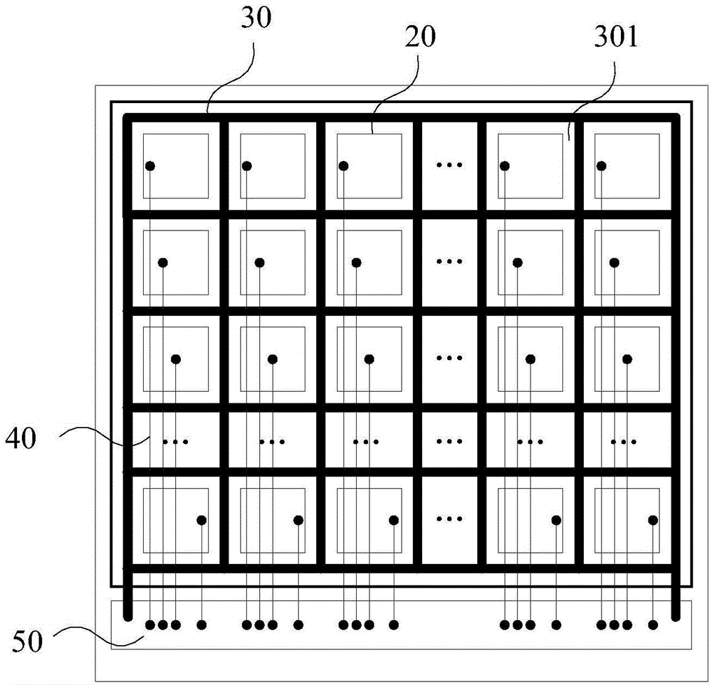
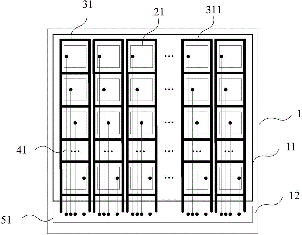
[0022] Please refer to image 3 , which is a schematic layout diagram of touch electrodes and conductive grids of a touch panel provided in a specific embodiment of the present invention. As shown in the figure, the touch panel includes a display area 11 and a non-display area 12, a plurality of touch electrodes 21 and a plurality of conductive grids ...


PUM


Abstract

The invention discloses a touch control panel and a liquid crystal display device. The touch control panel comprises a plurality of touch control electrodes and a plurality of conductive grids, wherein each touch control electrode is located inside one corresponding conductive grid; at least two touch control electrode groups are formed by the touch control electrodes, at least two conductive network units which are insulated from each other are formed by the conductive grids, and each conductive network unit corresponds to at least one touch control electrode group. Each touch control electrode group and the corresponding conductive network unit can be prevented from being interfered by other touch control electrode groups and conductive network units, and the generated voltage difference is reduced, so that the brightness difference between touch control electrode corresponding areas and conductive network unit corresponding areas during displaying is eliminated.

Description

technical field [0001] The invention relates to the field of touch technology, in particular to a touch panel and a liquid crystal display device. Background technique [0002] In existing touch implementation schemes, such as figure 1 As shown, the touch electrodes 20 are arranged in a matrix, and each touch electrode 20 is connected to a touch integrated circuit 50 through a touch signal line 40 . During the touch detection, each touch electrode 20 works in the same manner. During the touch detection process, the touch driving signal is generated by the touch integrated circuit 50 and provided to the touch electrode 20 through the touch signal line 40 . Make the touch electrode 20 carry a certain amount of charge; the touch integrated circuit 50 reads the change of the charging state of the touch electrode 20 through the touch signal line 40, and can determine which or Which touch electrodes 20 are touched can further determine the position of the touch point. Both the ...

Claims


Application Information

Patent Timeline
Patent Type & Authority Applications(China)
IPC IPC(8): G06F3/041G02F1/1333
CPCG06F3/0412G06F3/04166G06F3/0443G06F2203/04107
Inventor 赖青俊李静
Owner XIAMEN TIANMA MICRO ELECTRONICS
Why Eureka
Try Eureka