A fuel saver for motor vehicle fuel pipeline

A fuel pipe and fuel economizer technology, which is applied in the direction of machines/engines, mechanical equipment, engine components, etc., can solve the problems of rapid movement of unfavorable molecules, damage to fuel pipes, and inconvenient installation, so as to save fuel, reduce pollution, and prolong service life. Effect

Inactive Publication Date: 2018-03-27
高云良
View PDF9 Cites 0 Cited by
  • Summary
  • Abstract
  • Description
  • Claims
  • Application Information

AI Technical Summary

Problems solved by technology

In order to reduce fuel consumption and allow fuel to be fully burned, many manufacturers have launched different fuel economizers. Most of these fuel economizers have to be artificially damaged during installation, which is inconvenient to install, and often has a large volume and consumes fuel. Exhaust gas, fuel saving rate is generally low
It has changed the completely circular catalytic channel of other products. The oil in the tube is subjected to the same force around it. The actual effect is a kind of compression force, which is not conducive to the rapid movement of molecules. Therefore, it affects the pursuit of higher fuel saving rate.

Method used


Image

  • A fuel saver for motor vehicle fuel pipeline
  • A fuel saver for motor vehicle fuel pipeline
  • A fuel saver for motor vehicle fuel pipeline

Examples


Embodiment 1

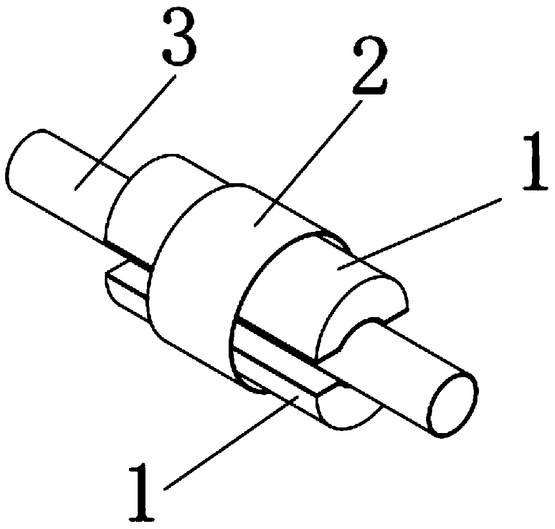
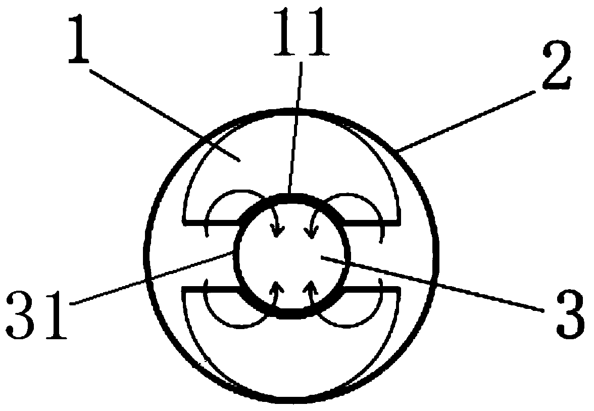
[0027] see attached Figure 1-4 As shown, the present embodiment 1 provides a fuel-saving device for a fuel pipe of a motor vehicle, which includes two fuel-saving units 1 and a fastening device 2 with the same structure, and the two fuel-saving units 1 are fixed to the motor vehicle through the fastening device 2. on the oil pipeline 3.

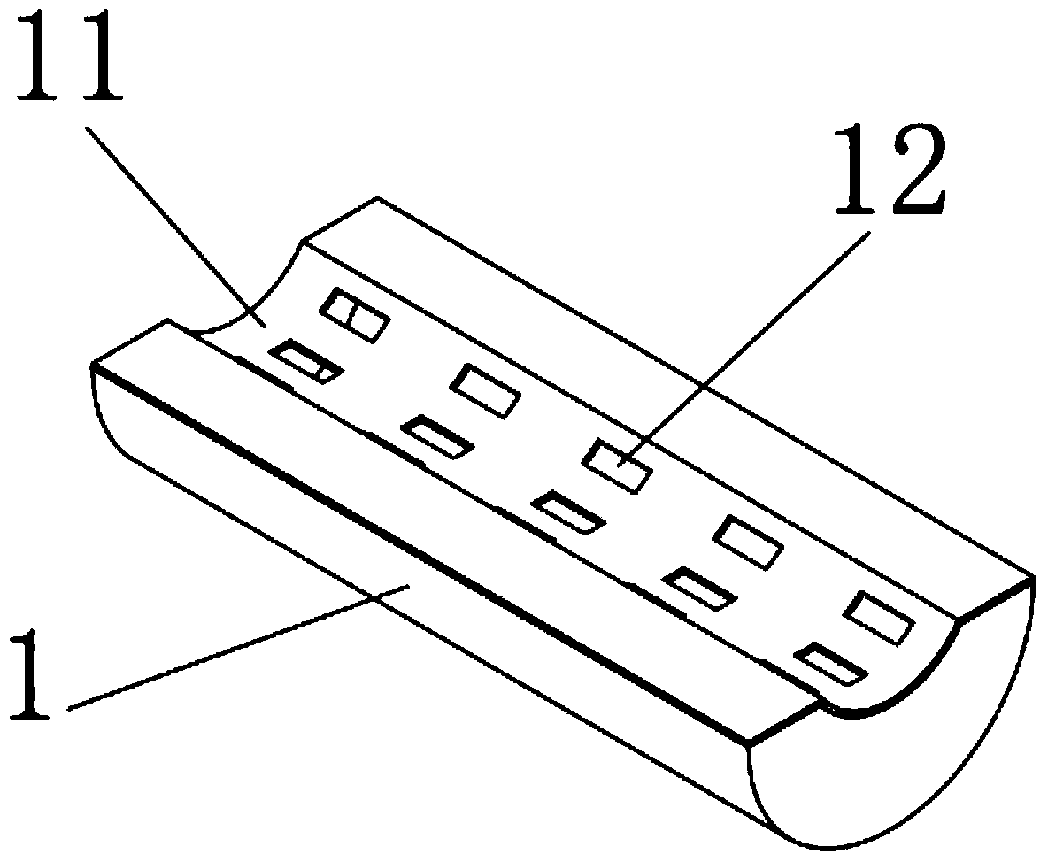
[0028] The two fuel-saving units 1 are arched and hollow inside to form a accommodating cavity 14. The two fuel-saving units 1 with the same structure are arranged correspondingly but not in contact with each other. The arches of the two fuel-saving units 1 form a The catalytic channel, the vehicle fuel pipe 3 is placed in the catalytic channel. One side of the two fuel-saving units 1 relative to the catalytic channel has a plurality of evenly distributed catalytic holes 12 , and the side of the fuel-saving unit relative to the catalytic channel may also be referred to as a groove wall 11 .

[0029] The accommodating cavity 14 is filled wi...

Embodiment 2

[0042] The content of the second embodiment is the same as that of the above-mentioned embodiment, the only difference is that the groove wall 11 on the inner side of the fuel-saving unit 1 of this embodiment is detachable, and the catalytic hole 12 is arranged along the axial direction of the groove. There are 3 rows, 7 in each row, and the fastening device 2 is a rope.

Embodiment 3

[0044] The content of the third embodiment is the same as the above-mentioned embodiment, the only difference is that the catalytic holes 12 of this embodiment are arranged in four rows along the axial direction of the groove wall 11, with five in each row. Device 2 is a card holder.


PUM


Abstract

The invention belongs to the technical field of energy conservation and relates to an oil economizer used for a locomotive oil delivery pipe. The oil economizer comprises two oil economizing units and a fastening device, the oil economizing units are fixed on the oil delivery pipe through the fastening device, and a nano catalytic material for catalyzing oil in the oil delivery pipe is arranged in each oil economizing unit. The oil economizer has the advantages that fuel oil is economized, combustion coefficient of the fuel oil can be increased, the fuel oil can be combusted fully, and average oil economizing rate can reach more than 22.6%; horsepower is increased, power performance is improved as the fuel oil coefficient is increased, and climbing ability and acceleration performance are improved by more than 16%; service life is prolonged, accumulation of carbide in an engine can be prevented, wear is reduced, accumulated carbon of the engine is eliminated after normal traveling for 200km, torque is further increased, the engine is smoother in running and silent, noise is lowered, and service life of the engine is prolonged.

Description

technical field [0001] The invention belongs to the technical field of energy saving, and relates to an economizer used for an oil pipe of a motor vehicle. Background technique [0002] At present, there are many types and models of motor vehicles, especially automobiles and motor vehicles, with different structures and different levels of fuel consumption. In order to reduce fuel consumption and allow the fuel to be fully burned, many manufacturers have introduced different fuel-saving devices. Most of these fuel-saving devices require man-made damage to the fuel pipeline during installation, which is inconvenient to install, and is often bulky, fuel-consuming, and cannot be smoked and reduced. Exhaust gas, fuel saving rate is generally low. The completely circular catalytic channel of other products is changed, and the oil in the tube is subjected to the same force around it. The actual effect is a compression force, which is not conducive to the rapid movement of molecul...

Claims


Application Information

Patent Timeline
Patent Type & Authority Patents(China)
IPC IPC(8): F02M27/02B01J27/224
CPCY02T10/12
Inventor 高云良
Owner 高云良
Why Eureka
Try Eureka