Main optical channel power test method and apparatus

A power test and channel technology, applied in the field of communication, can solve problems such as the difficulty of applying super channel optical signals

Active Publication Date: 2015-10-14
CHINA ACADEMY OF INFORMATION & COMM
View PDF4 Cites 5 Cited by
  • Summary
  • Abstract
  • Description
  • Claims
  • Application Information

AI Technical Summary

Problems solved by technology

[0005] The existing WDM system main optical channel power test is based on the ITU-T traditional 50GHz fixed spectrum interval for th

Method used


Image

  • Main optical channel power test method and apparatus
  • Main optical channel power test method and apparatus
  • Main optical channel power test method and apparatus

Examples


Embodiment Construction

[0022] In order to make the object, technical solution and advantages of the present invention clearer, the technical solution of the present invention will be described in detail below with reference to the accompanying drawings and examples.

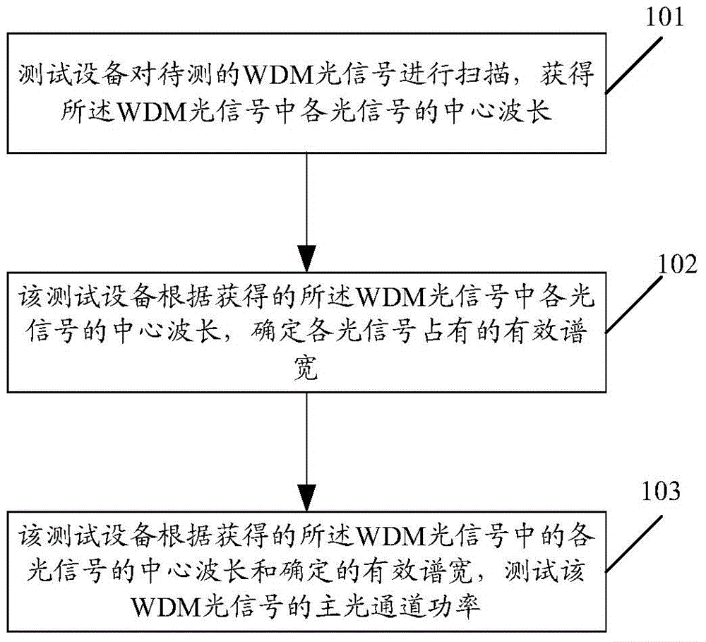
[0023] In the embodiment of the present application, a main optical channel power testing method is proposed, which is applied to a multi-subcarrier multiplexing optical communication system, and can perform main optical channel power measurement on multi-subcarrier multiplexing super channel spectra with flexible spectrum intervals.

[0024] The equipment used to test the optical channel power in the embodiment of the present application is called a testing equipment, and the testing equipment may be a high-resolution spectrometer, or may be a device with a high-resolution spectrometer function.

[0025] see figure 1 , figure 1 It is a schematic diagram of the power test flow of the main optical channel in the embodiment of the prese...


PUM


Abstract

The invention provides a main optical channel power test method. The method includes the following steps that: WDM optical signals to be tested are scanned, so that the central wavelengths of optical signals in the WDM optical signals can be obtained; effective spectral widths occupied by the optical signals can be determined according to the central wavelengths of the optical signals in the WDM optical signals; and the main optical channel power of the WDM optical signals is tested according to the central wavelengths of the optical signals in the WDM optical signals and the determined effective spectral widths. Based on the same conception as above, the invention also provides a main optical channel power test apparatus. With the main optical channel power test apparatus adopted, main optical channel power measurement of multi-sub-carrier multiplexed super channel spectra of flexible spectrum intervals can be performed flexibly.

Description

technical field [0001] The invention relates to the field of communication technology, in particular to a method and device for testing the power of a main optical channel. Background technique [0002] With the rapid development of new Internet services, the demand for the capacity and bandwidth of optical fiber bearer network is increasing day by day. In the 100 Gbit After the optical communication system of / s (abbreviated as 100G) has matured and been commercialized on a large scale, the ultra-100G optical communication system represented by 400Gbit / s (abbreviated as 400G) has also begun to enter the stage of laboratory testing and trial commercialization. [0003] The ultra-100G multi-subcarrier multiplexing optical communication system aims to improve spectral efficiency and transmission distance, and introduces new technical features such as high-order modulation formats, multi-subcarrier multiplexing super channels, and flexible spectrum spacing at the physical layer...

Claims


Application Information

Patent Timeline
IPC IPC(8): H04B10/079
Inventor 赵鑫赖俊森赵文玉张海懿汤瑞汤晓华吴冰冰李少晖
Owner CHINA ACADEMY OF INFORMATION & COMM
Why Eureka
Try Eureka