Miniature antenna servo apparatus

A servo device and antenna technology, applied in antennas, electrical components, etc., can solve problems such as difficult miniaturization, occupying payload space, and complex structure, and achieve the effect of increasing the rotation angle, reducing the moment of inertia, and simple mechanism structure

Active Publication Date: 2016-01-27
SHANGHAI RADIO EQUIP RES INST
View PDF3 Cites 7 Cited by
  • Summary
  • Abstract
  • Description
  • Claims
  • Application Information

AI Technical Summary

Problems solved by technology

[0006] (1) Complex structure
Whether it is the azimuth channel or the pitch channel, it is driven by multi-stage gears, which requires high machining accuracy for parts, especially arc-toothed parts, and the manufacturing cost of the entire servo mechanism is relatively high.
[0007] (2) Difficult to miniaturize
Due to the complexity of the existing servo mechanism, many parts and large volume, it is difficult to meet the requirements of product miniaturization
[0008] (3) Insufficient available space
Components such as angle measuring components and gyro components are placed inside the tooth arc, occupying the space of the payload, resulting in insufficient effective space
[0009] (4) The envelope of the detection component is large
The space occupied by the detection component during the movement is its motion envelope. Since most of the detection components are fixed on the pitch frame, the distance between the front face of the detection component and the rotation center is relatively large, and the envelope size is large during the rotation process. Meet the constraint requirements of compact space location

Method used


Image

  • Miniature antenna servo apparatus
  • Miniature antenna servo apparatus
  • Miniature antenna servo apparatus

Examples


Embodiment Construction

[0042] The present invention will be further elaborated below by describing a preferred specific embodiment in detail in conjunction with the accompanying drawings.

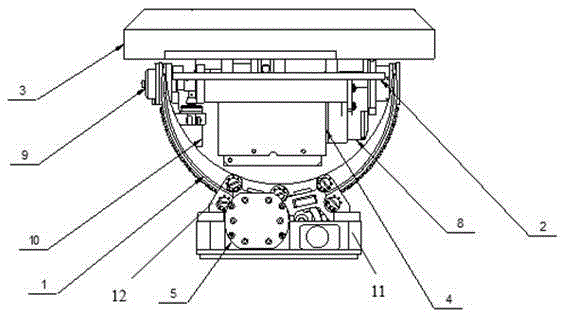
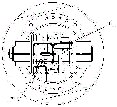
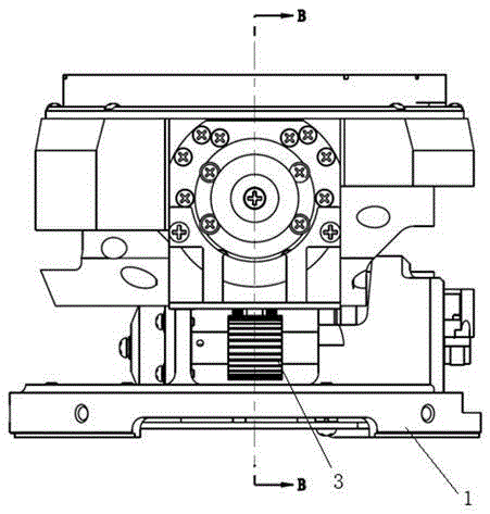
[0043] Such as image 3 , 4 , shown in 5, a kind of miniaturized antenna servo device, comprises: base 1; Azimuth channel motor 2, it is arranged on the base 1; Azimuth channel motor gear 3, it is driven by azimuth channel motor 2; A pair of sector gear 4, It is located on the upper part of the base 1 and meshes with the azimuth channel motor gear 3; the azimuth channel includes the azimuth channel main shaft 6; the pitch channel includes the pitch channel main shaft 71, which is perpendicular to the azimuth channel main shaft 6; The channel main shaft 6 and a pair of sector gears 4 are integrally connected by screws. When the control system controls the rotation of the azimuth channel motor 2, the azimuth channel motor gear 3 drives the sector gear 4 to rotate, so that the azimuth channel main shaft 6 and the p...


PUM


Abstract

The invention discloses a miniature antenna servo apparatus. The miniature antenna servo apparatus comprises a pedestal, an orientation channel motor which is arranged on the pedestal, an orientation channel motor gear which is driven by the orientation channel motor, a pair of sector gears, an orientation channel and a pitching channel, wherein the pair of sector gears are arranged on the upper part of the pedestal and are meshed with the orientation channel motor gear; the orientation channel includes an orientation channel principal axis; the pitching channel includes a pitching channel principal axis which is perpendicular to the orientation channel principal axis; the pitching channel principal axis, the orientation channel principal axis and the pair of sector gears are connected as one body; and the orientation channel motor gear drives the sector gears to rotate so that the orientation channel principal axis and the pitching channel principal axis can also rotate around the hole axis at the upper part of the pedestal synchronously. The miniature antenna servo apparatus is simple in structure and is miniaturized, and has the advantages of being large in the installable detection assembly, being high in the bearable load moment of inertia, being able to realize the maximum compound angle limiting function, and being low in cost.

Description

technical field [0001] The invention relates to the structural design field of a servo mechanism, in particular to a miniaturized antenna servo device. Background technique [0002] The space structure size required for target detection and tracking components is getting smaller and smaller, and the original servo mechanism tracking platform is difficult to meet the use requirements, so it is necessary to develop a new miniaturized servo mechanism. [0003] The existing servo mechanism mostly adopts tooth arc structure, such as figure 1 , 2 As shown, the azimuth channel motor drives the tooth arc through the gear reducer, and the pitch channel motor drives through the gear reducer, so that the load has two degrees of freedom to rotate, and the cone angle scanning is realized. In the space formed, effective loads such as detection components are installed in the tooth arc space. [0004] In the existing tooth arc mechanism, the tooth arc 1 is not only the transmission gear...

Claims


Application Information

Patent Timeline
Patent Type & Authority Applications(China)
IPC IPC(8): H01Q3/10
Inventor 黄海涛马亮王光强杨新国
Owner SHANGHAI RADIO EQUIP RES INST
Why Eureka
Try Eureka