Control grip clutch mechanism of processing machinery

A technology of processing machinery and clutch mechanism, which is applied in the direction of mechanically driven clutches, mutually meshing clutches, clutches, etc., and can solve problems such as personnel injury, tripping, and item damage

Active Publication Date: 2017-10-20
KING YU FANG ENTERPRISE
View PDF7 Cites 0 Cited by
  • Summary
  • Abstract
  • Description
  • Claims
  • Application Information

AI Technical Summary

Problems solved by technology

[0003] However, the operation wheel is not designed to be detached from the shaft at any time. Therefore, when the automatic tool feeder is activated, the shaft that drives the displacement of the processing platform will also drive the operation wheel to rotate. If the operator does not pay attention and gets too close, the It may be caught by the handle of the rotating operation wheel during processing, causing personal injury; or the handle may knock over adjacent items due to the rotation of the operation wheel, resulting in damage to the item

Method used


Image

  • Control grip clutch mechanism of processing machinery
  • Control grip clutch mechanism of processing machinery
  • Control grip clutch mechanism of processing machinery

Examples


Embodiment Construction

[0032] The following examples illustrate possible implementations of the present invention, but they are not intended to limit the protection scope of the present invention and are described in advance.

[0033] see Figure 1 to Figure 8 What is shown in the figure is the selected embodiment structure of the present invention, which is for illustration only, and is not limited by this structure in the patent application.

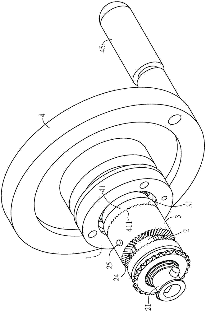
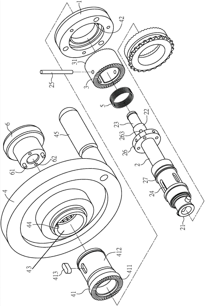
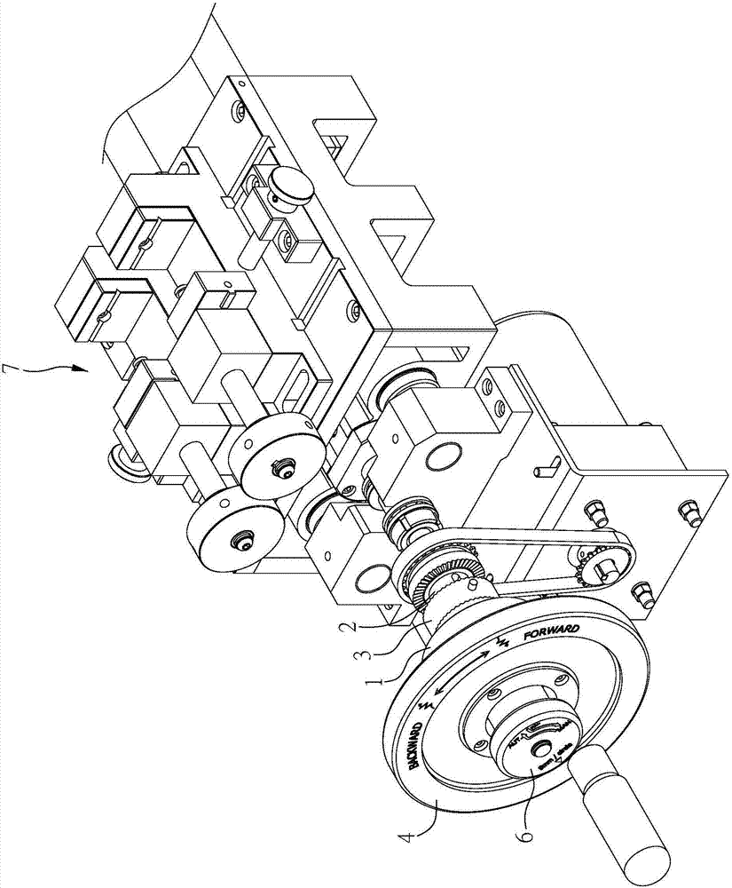
[0034] This embodiment provides a control handle clutch mechanism of a processing machine, such as Figure 1 to Figure 2 As shown, it includes a pivot joint seat 1, an axial tube 2, a movable block 3, an operation wheel 4, an elastic member 5, and a control member 6. The aforementioned processing machine takes a cutting machine as an example in this embodiment, as image 3 As shown, the flying control grip clutch mechanism of this embodiment is combined with the transmission mechanism 7 of the cutting machine, wherein:

[0035] Such as figure 2 and Fig...


PUM


Abstract

A control grip clutch mechanism for a processing machine, which is a pivot joint seat combined with the processing machine; an axis tube penetrates the pivot joint seat, and an insertion rod is inserted through the axis tube, and one end of the insertion rod is at the axis center The tube is exposed; a movable block is sleeved on the axial tube, and the movable block is connected with the insertion rod on the outer periphery of the axial tube; a positioning block is provided on one side of the operation wheel, and the positioning block is coaxially pivoted on the axial tube; The control part is combined with the end of the plunger. The control part can be pulled up to drive the movable block to move between a first position and a second position through the axial displacement of the plunger. In the first position, the movable block is out of position. block; in the second position, the movable block is engaged with the positioning block, so that the rotation of the operating wheel can drive the axis tube to rotate, thereby constituting the present invention.

Description

technical field [0001] The invention relates to a control handle of a processing machine, in particular to a control handle clutch mechanism for a processing machine. Background technique [0002] Known processing machines, such as milling machines or lathes, usually have a processing platform capable of horizontal displacement, which can drive the processing platform to move in at least one axial direction through the shaft in manual mode through the manual rotation of the operating wheel, or can be automatically The actuation of the feeding device makes the processing platform automatically shift between a preset stroke in the automatic feeding mode. [0003] However, the operation wheel is not designed to be detached from the shaft at any time. Therefore, when the automatic tool feeder is activated, the shaft that drives the displacement of the processing platform will also drive the operation wheel to rotate. If the operator does not pay attention and gets too close, the...

Claims


Application Information

Patent Timeline
Patent Type & Authority Patents(China)
IPC IPC(8): F16D11/00
Inventor 谢益铜
Owner KING YU FANG ENTERPRISE
Why Eureka
Try Eureka