Fixed shaft type dynamic magnetic power-driven actuator

An actuator, fixed-axis technology, applied in electrical components, electromechanical devices, etc., can solve the problems of fatigue fracture, large magnetic field strength, occupying installation space, etc., achieve good fatigue characteristics, ensure anisotropic characteristics, and facilitate installation. Effect

Active Publication Date: 2016-04-27
中国船舶集团有限公司第七一一研究所
View PDF4 Cites 3 Cited by
  • Summary
  • Abstract
  • Description
  • Claims
  • Application Information

AI Technical Summary

Problems solved by technology

[0003] The cage of the electric actuator usually adopts a leaf spring, which is easy to cause fatigue fracture under large displacement and long-term working conditions, and is easily damaged under impact, which cannot guarantee long-term operation requirements
At present, the actuator is basically a cylindrical structure, and most of the active control objects including diesel engines, the installation position of the actuator is not a circle, but a rectangular or irregular structure; most of the installation methods are combined by screws The installation of the transition plate is not very convenient and takes up a part of the limited installation space; and some actuators are equipped with coil holders, which occupy a part of the magnetic field gap with a large magnetic field strength.

Method used


Image

  • Fixed shaft type dynamic magnetic power-driven actuator

Examples


Embodiment Construction

[0010] The application will be further described in detail below in conjunction with the accompanying drawings and embodiments. It should be understood that the specific embodiments described here are only used to explain related inventions, rather than to limit the invention. It should also be noted that, for ease of description, only parts related to the invention are shown in the drawings.

[0011] It should be noted that, in the case of no conflict, the embodiments in the present application and the features in the embodiments can be combined with each other. The present application will be described in detail below with reference to the accompanying drawings and embodiments.

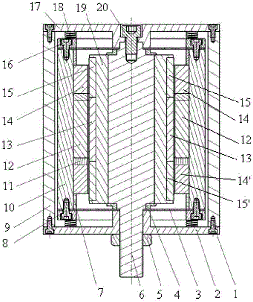
[0012] Such as figure 1 As shown, the present application provides a fixed-axis type moving magnet electric actuator, including a housing 9, a first end cover 17 and a second end cover 2 connected to the housing 9, a stator located in the housing 9, and a mover And the elastic support structure a...


PUM


Abstract

The application discloses a fixed shaft type dynamic magnetic power-driven actuator. The fixed shaft type dynamic magnetic power-driven actuator comprises a shell, a first end cover, a second end cover, a stator, a rotor and an elastic support structure and also comprises a fixed shaft, wherein the first end cover and the second end cover are connected with the shell, the stator and the rotor are arranged in the shell, the stator is arranged at the outer side of the fixed shaft, the rotor is arranged at the periphery of the stator, the elastic support structure is connected with the rotor and the fixed shaft, one end of the fixed shaft is fixedly connected with the first end cover and arranged at the inner side of the first end cover, the other end of the fixed shaft extends out of the second end cover, a part, extending out of the second end cover, of the fixed shaft is provided with a thread structure, and the thread structure is used for being screwed into an installation hole of a controlled device. With a mode of the fixed shaft and bolt output, the fixed shaft type dynamic magnetic power-driven actuator is convenient to install; the elastic support structure is connected with the rotor and the fixed shaft, the rotor can be accurately positioned, various characteristics of the actuator are ensured, and favorable fatigue property is also achieved; and with the adoption of a rectangular structure, relatively high output of the actuator can be guaranteed, and a limited installation space also can be fully utilized.

Description

technical field [0001] The invention relates to the technical field of active vibration control of equipment, in particular to a fixed-axis type moving magnet electric actuator. Background technique [0002] The actuator is an important component in the active vibration control system. Its working principle is to apply control actions to the controlled object or system according to the output signal of the controller, and output force according to the required method, thereby changing the response of the controlled object or system. . At present, commonly used actuators include servo pneumatic, hydraulic, electromagnetic / dynamic and new intelligent actuators made of intelligent materials, such as piezoelectric materials, shape memory alloys, electric / magnetostrictive materials and electric / magnetic Rheological materials, etc. The design and selection of the actuator is closely related to the application, and is constrained by volume, structure form, demand force, demand po...

Claims


Application Information

Patent Timeline
Patent Type & Authority Applications(China)
IPC IPC(8): H02K33/00
CPCH02K33/00
Inventor 殷长春支李峰泮江江魏新元张欢王志刚
Owner 中国船舶集团有限公司第七一一研究所
Why Eureka
Try Eureka