
An automatic pouring machine
A technology of automatic pouring and ladle
- Summary
- Abstract
- Description
- Claims
- Application Information
AI Technical Summary
Problems solved by technology
Method used
Image

Examples
specific Embodiment approach
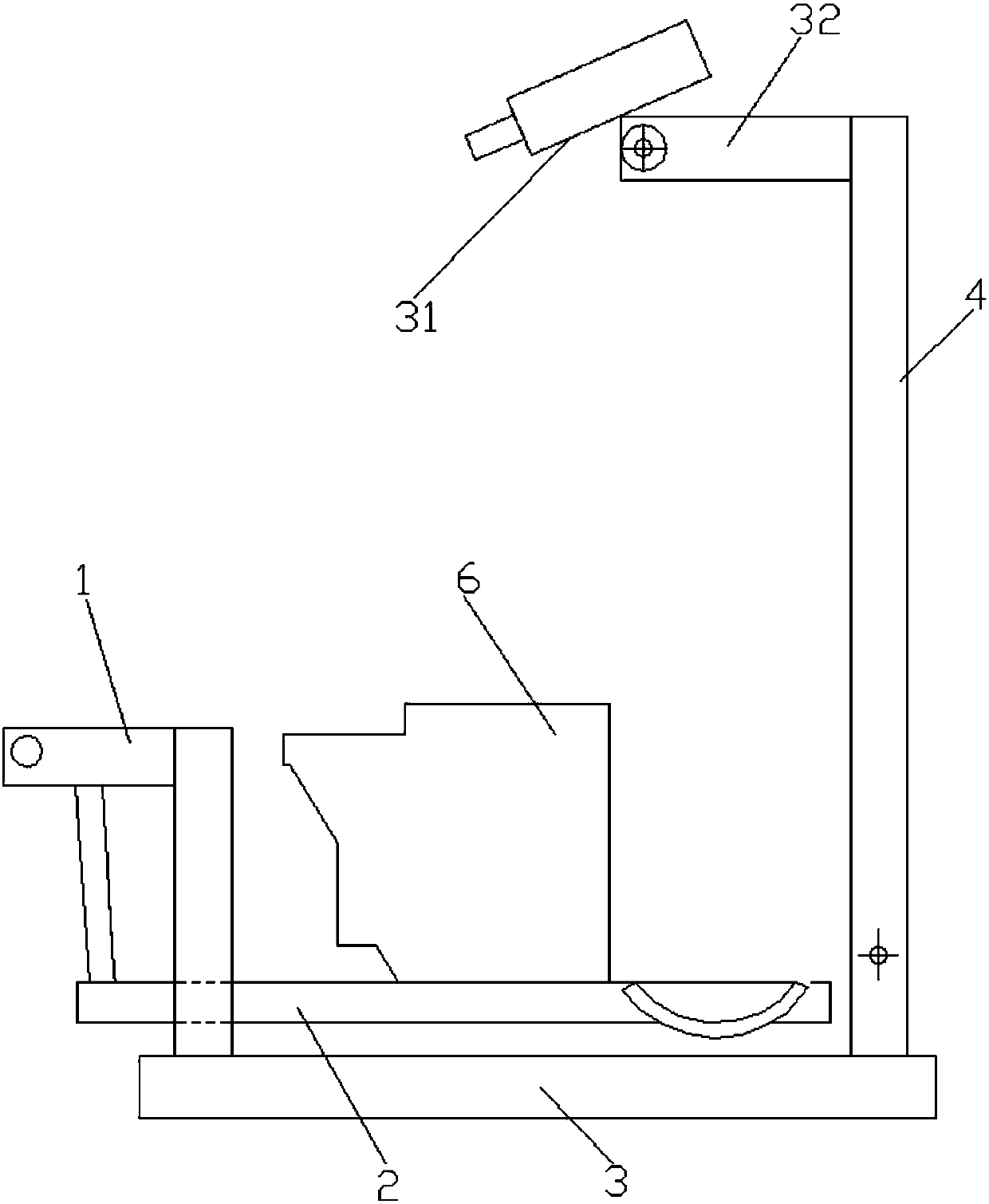
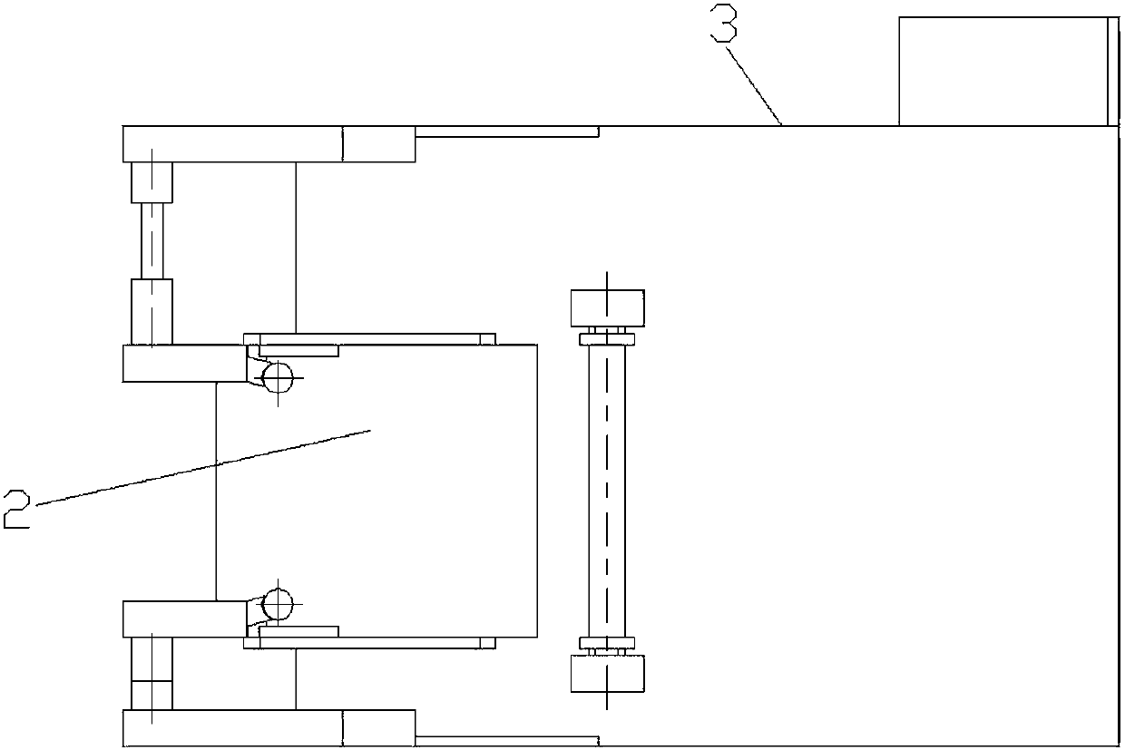
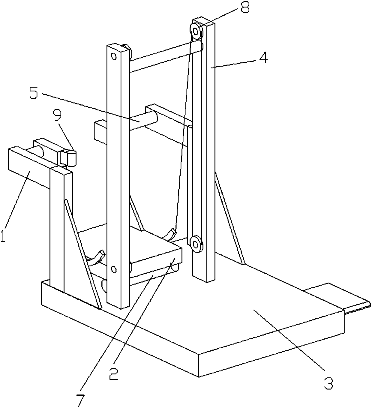
[0043] like Figure 1-17As shown, it shows a specific embodiment of the present invention. As shown in the figure, the present invention discloses an automatic pouring machine, which includes an upper platform 3, and a bracket for rotating and installing a rotating bracket 2 is arranged in parallel on the upper platform. 1 and a frame 4 for installing the pulley; the frame is arranged at the rear of the support; the frame includes two columns arranged parallel to each other, and the pulley includes an upper pulley 8 and a lower pulley, and the upper pulley and the lower pulley are rotatably installed on On the surface of the opposite side of the two uprights; the end of the rotating bracket near the frame side is fixedly connected with a rope 27, and the far end of the rope is pulled by a motor after passing through the upper pulley and the lower pulley; the rotating bracket The end on the side away from the frame is rotatably mounted on the bracket;
[0044] As shown in the ...
PUM
 Abstract
Description
Claims
Application Information