Efficient hardware cleaning device

A cleaning device and hardware technology, applied in the field of mechanical equipment, can solve problems such as reducing work efficiency, increasing maintenance costs, and parts damage, and achieving the effects of reducing maintenance costs, improving work efficiency, and saving water resources

Active Publication Date: 2016-11-09
NANTONG HANGTAI MARINE MACHINERY CO LTD
View PDF5 Cites 11 Cited by
  • Summary
  • Abstract
  • Description
  • Claims
  • Application Information

AI Technical Summary

Problems solved by technology

[0002] In large-scale mechanical equipment, some precision mechanical parts are generally composed of small hardware parts. It is only under the joint action of these hardware parts that large-scale mechanical equipment can be safely operated and produced. However, these small After the hardware parts are used for a long time, the surface will be covered with a layer of dust. This dust not only affects the operation of mechanical equipment, but also reduces the work efficiency. Therefore, these parts will be removed for cleaning every once in a while.
[0003] The traditional hardware parts cleaning device is to put the parts together for cleaning. However, because there are many parts and they are piled up for cleaning, the cleaning will not be clean. In addition, the parts are put together for cleaning, which will inevitably cause collisions. It may cause damage to some parts, which not only affects the use of mechanical equipment, but also increases maintenance costs

Method used


Image

  • Efficient hardware cleaning device
  • Efficient hardware cleaning device
  • Efficient hardware cleaning device

Examples


Embodiment Construction

[0015] The following will clearly and completely describe the technical solutions in the embodiments of the present invention with reference to the accompanying drawings in the embodiments of the present invention. Obviously, the described embodiments are only some, not all, embodiments of the present invention. Based on the embodiments of the present invention, all other embodiments obtained by persons of ordinary skill in the art without making creative efforts belong to the protection scope of the present invention.

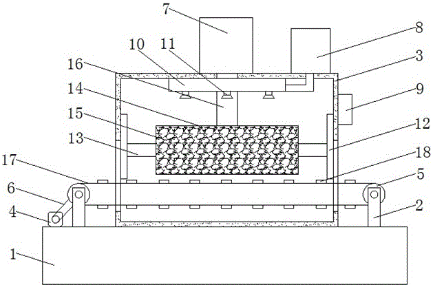
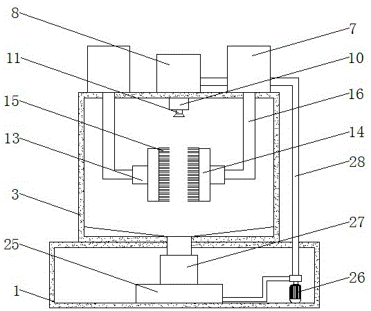
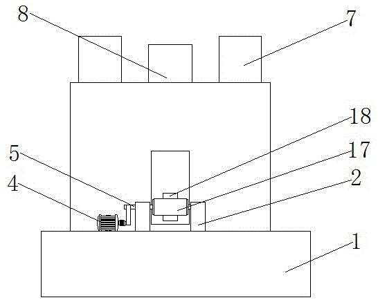
[0016] see Figure 1-4 , the present invention provides a technical solution: a high-efficiency hardware cleaning device, including a base 1, the top of the base 1 is symmetrically provided with support rods 2, and a cleaning box 3 is fixedly installed on the top of the base 1 and between the support rods 2, The top of the base 1 and the left side of the support rod 2 are also equipped with a first motor 4, the support rod 2 is movably connected with a rotatin...


PUM


Abstract

The invention discloses an efficient hardware cleaning device. The efficient hardware cleaning device comprises a base, wherein support rods are symmetrically arranged at the top of the base, a cleaning box is fixedly mounted at the top of the base and located between the support rods, a first motor is further mounted at the top of the base and located on the left side of the corresponding support rod, rotating shafts are movably connected onto the support rods, one end of each rotating shaft penetrates through the corresponding support rod and extends out of the support rod, and an output shaft of the first motor is in transmission connection with one side, extending out of the corresponding support rod, of one rotating shaft through a first belt. According to the efficient hardware cleaning device, by the aid of a conveying belt and a fixing block connected onto the conveying belt, the problem that hardware is stacked together to be cleaned is solved, damage to the hardware due to collision is avoided, use of mechanical equipment is facilitated, a crank connecting rod can drive a brush to move up and down, the cleaning device can comprehensively clean the hardware, and the working efficiency is improved.

Description

technical field [0001] The invention relates to the technical field of mechanical equipment, in particular to an efficient hardware cleaning device. Background technique [0002] In large-scale mechanical equipment, some precision mechanical parts are generally composed of small hardware parts. It is only under the joint action of these hardware parts that large-scale mechanical equipment can be safely operated and produced. However, these small After a long time of use of hardware parts, the surface will be covered with a layer of dust, which not only affects the operation of mechanical equipment, but also reduces work efficiency. Therefore, these parts will be removed for cleaning every once in a while. [0003] The traditional hardware parts cleaning device is to put the parts together for cleaning. However, because there are many parts and they are piled up for cleaning, the cleaning will not be clean. In addition, the parts are put together for cleaning, which will inev...

Claims


Application Information

Patent Timeline
Patent Type & Authority Applications(China)
IPC IPC(8): B08B3/02B08B1/00
CPCB08B1/002B08B1/008B08B3/02
Inventor 冯才南
Owner NANTONG HANGTAI MARINE MACHINERY CO LTD
Why Eureka
Try Eureka