Experimental mouse caudal vein micro injector

A tail vein and laboratory mouse technology, applied in the field of medical devices, can solve the problems of inconvenient operation, inaccurate dosage, and death of laboratory mice, and achieve the effects of saving reagents, ensuring accuracy, and saving experimental implementation.

Inactive Publication Date: 2016-11-16
王炎强
View PDF9 Cites 3 Cited by
  • Summary
  • Abstract
  • Description
  • Claims
  • Application Information

AI Technical Summary

Problems solved by technology

At present, the needles and pipe diameters of the micro-injectors used for the tail vein injection of experimental rats are long, and the micro-injectors are directly connected to the injection needles. The operation is inconvenient during injection, and most of them are manual operations. The speed and dose of injection are not accurate. In addition, due to The wall of the tail vein of experimental rats is thin. When the experimental rats are struggling, it is easy for the needles to come out and damage the blood vessels. Although some measures such as immobilizing the rats, administering anesthesia, or cooperating with two people can be taken in the experiment, once some experiments require no Satisfaction or poor control of the dose of anesthesia injected can easily lead to the death of experimental mice. For example, anesthetics were injected during the preparation of the model. Rats die, time-consuming and labor-intensive, and even lead to experiment failure

Method used


Image

  • Experimental mouse caudal vein micro injector

Examples


Embodiment Construction

[0025] For ease of understanding, the technical solutions of the present invention are further specifically described below in conjunction with the accompanying drawings and through embodiments:

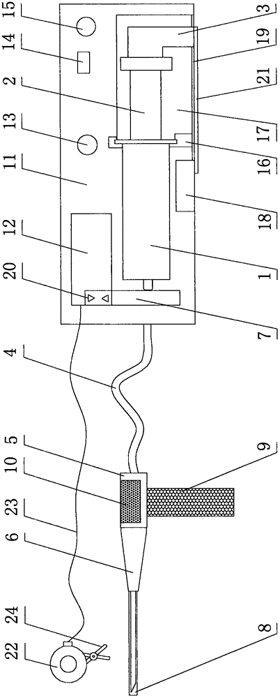
[0026] Such as figure 1 As shown, a tail vein microinjector for experimental rats includes a syringe 1 , a push rod 2 , an electric push block 3 , an electronic pump 11 , a needle holder 5 and a short needle 6 .

[0027] The push rod 2 is movably arranged in the syringe 1 .

[0028] The front end of the syringe 1 is provided with a flexible hose 4 , and the front end of the flexible hose 4 is connected with the needle holder 5 .

[0029] The short needle 6 is detachably arranged at the front end of the needle holder 5 .

[0030] The syringe 1 is detachably arranged on the electronic pump 11 through the fixing block 16 .

[0031] A motor 18 is arranged on the electronic pump 11 , and a toothed bar 21 is arranged under the motor 18 ; the toothed bar 21 is driven by the motor 18 .

...


PUM


Abstract

The invention discloses an experimental mouse caudal vein micro injector, which comprises a syringe tube, a push rod, an electric pushing block, an electronic pump, a syringe needle base, a soft hose and a syringe needle, wherein the push rod is arranged in the syringe tube in a movable mode; and a micro flow meter is arranged on the electronic pump. The back end of the micro flow meter is connected to the syringe tube; the front end of the micro flow meter is provided with the flexible soft hose; the front end of the flexible soft hose is connected to the syringe needle base; the needle head is detachably arranged at the front end of the syringe needle base; and the syringe tube is detachably arranged on the electronic pump. A motor and a toothed strip are arranged on the electronic pump; the motor is meshed with the toothed strip by virtue of a gear; the electronic pushing block is arranged on the toothed strip; a sliding guide rail is arranged on the electronic pump; a display screen, a timer and a pushing block sliding cavity are arranged on the electronic pump; the display screen and the micro flow meter are connected; the timer and the motor are connected; and flow regulating buttons are arranged on the display screen. With the implementation of the micro injector disclosed by the invention, it can precisely control an injection speed and conduct metering, which is conducive to the accuracy of experimental results; the syringe needle does not easily become fallen and blood vessels are not easily damaged;and caudal vein injection can be completed by one person; therefore, the micro injector is labor-saving and is convenient to operate.

Description

technical field [0001] The invention belongs to the technical field of medical devices, and in particular relates to a tail vein microinjector for experimental rats. Background technique [0002] Due to the needs of medical experiments, some drugs or reagents must be administered through the tail vein of experimental mice, and after immunization, serum antibody levels need to be measured by tail blood sampling. These procedures require the use of microinjectors. At present, the needles and pipe diameters of the micro-injectors used for the tail vein injection of experimental rats are long, and the micro-injectors are directly connected to the injection needles. The operation is inconvenient during injection, and most of them are manual operations. The speed and dose of injection are not accurate. In addition, due to The wall of the tail vein of experimental rats is thin. When the experimental rats are struggling, it is easy for the needles to come out and damage the blood v...

Claims


Application Information

Patent Timeline
Patent Type & Authority Applications(China)
IPC IPC(8): A61D7/00
CPCA61D7/00
Inventor 王炎强
Owner 王炎强
Why Eureka
Try Eureka