

A humidity-regulating bidirectional motor structure suitable for smart homes
Patent Information
- Authority / Receiving Office
- CN · China
- Patent Type
- Patents(China)
- Current Assignee / Owner
- SUZHOU FUTENG INTELLIGENT TECH CO LTD
- Publication Date
- 2020-11-03
Smart Images
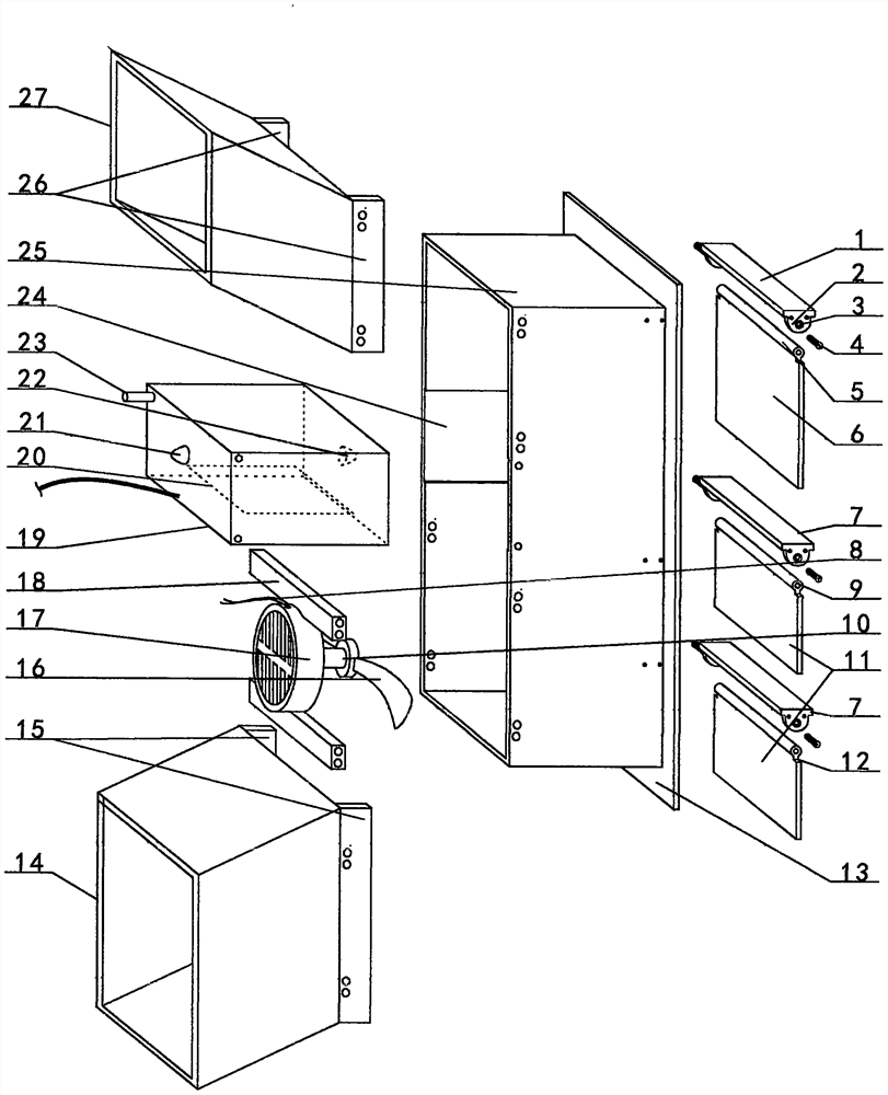
Figure 1 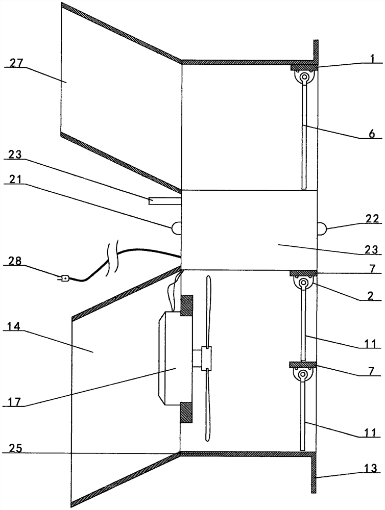
Figure 2 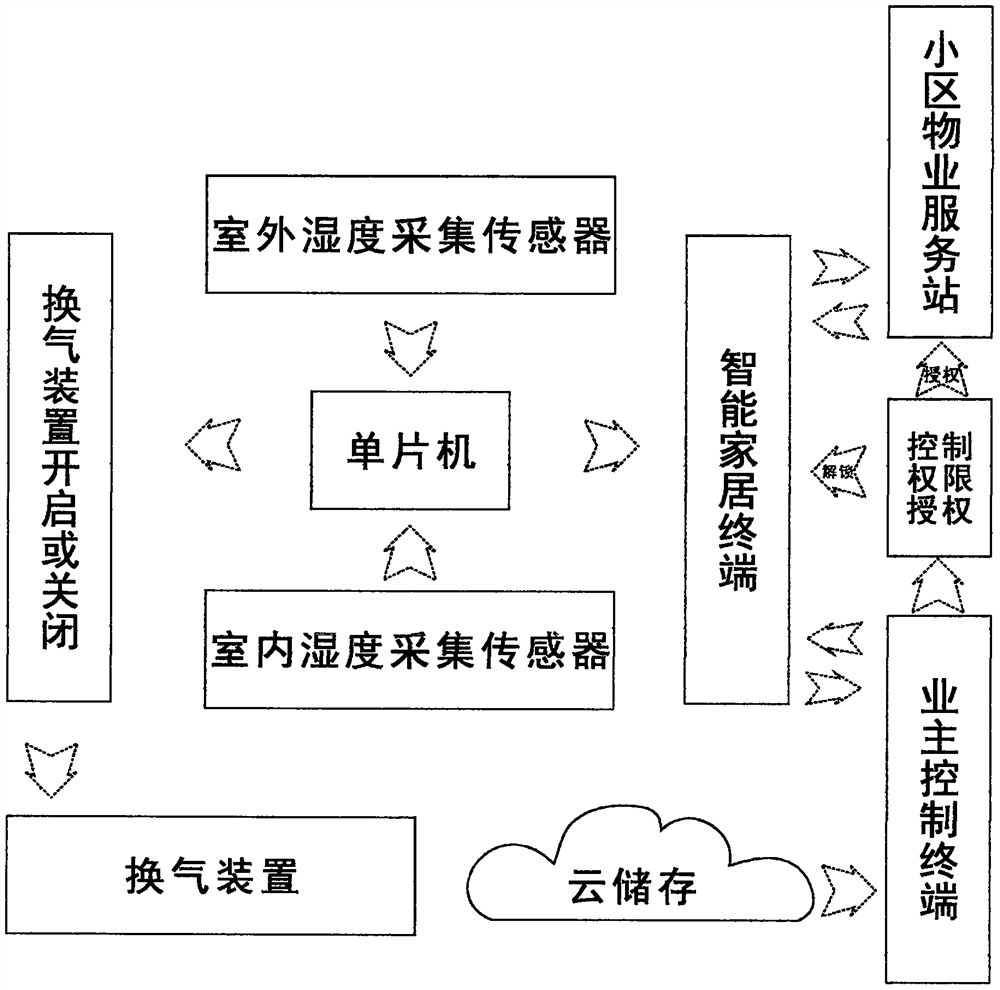
Figure 3
Abstract
Description
【Technical field】
[0001] The invention relates to a bidirectional motor structure, in particular to a humidity regulating bidirectional motor structure suitable for smart home. 【Background technique】
[0002] With the continuous improvement of people's living standards, more and more people choose to use their annual leave or Golden Week to travel, and many people also choose to travel abroad; retired northerners who have lived in some big cities for many years usually choose to go to the south in winter. Because of the above-mentioned reasons, the home is unoccupied for a long time, so there will be mildew in the home in some humid environments, especially during the rainy season and when neighbors use heating in winter. There is no air circulation in the home for a long time. Once you go out and come home, you will find that not only the smell is unpleasant, but also many household appliances, furniture, or clothes have mold spots, which are caused by the lack of air circu...