Al technical title is built by PatSnap Al team. It summarizes the technical point description of the patent document.
A technology of a seeder and a seeder tube, which is applied in sowing, agriculture, application, etc., and can solve the problem of single function of the seeder
Active Publication Date: 2017-05-10
JILIN ACAD OF AGRI SCI
View PDF4 Cites 3 Cited by
Summary
Abstract
Description
Claims
Application Information
AI Technical Summary
This helps you quickly interpret patents by identifying the three key elements:
Problems solved by technology
Method used
Benefits of technology
Problems solved by technology
[0003] Yet, most of the seeders in the prior art have the shortcoming of single function
Method used
Image
Click on the blue label to locate the original text in one second.
Reading with bidirectional positioning of images and text.
Examples
Embodiment 1
[0035] Example 1, see Figure 1 to Figure 3 as shown,
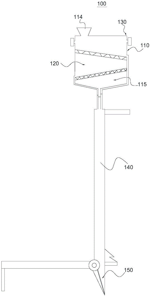
[0036] see figure 1 , as shown in the figure, this embodiment provides a seeder 100 , including a housing 110 , a screening mechanism 120 , an impurity removal mechanism 130 , a seeding tube 140 and a nozzle 150 .
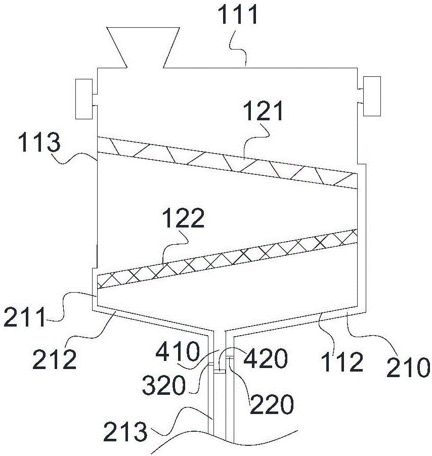
[0037] In this embodiment, the shape of the housing 110 is not specifically limited. Preferably, the cross section of the housing 110 perpendicular to its own axis (not shown in the figure) is circular. see figure 2 , the casing 110 has a first side wall 111 and a second side wall 112 respectively opposite to each other, and a third side wall 113 connected between the first side wall 111 and the second side wall 112 .
[0038] see figure 1 , in this embodiment, a feeding portion 114 and a discharging portion 115 are respectively provided on opposite sides of the casing 110 . see figure 1 and image 3 , preferably, a feeding chamber 116 , a first screening chamber 117 and a second screening chamber 118 ...
Embodiment 2
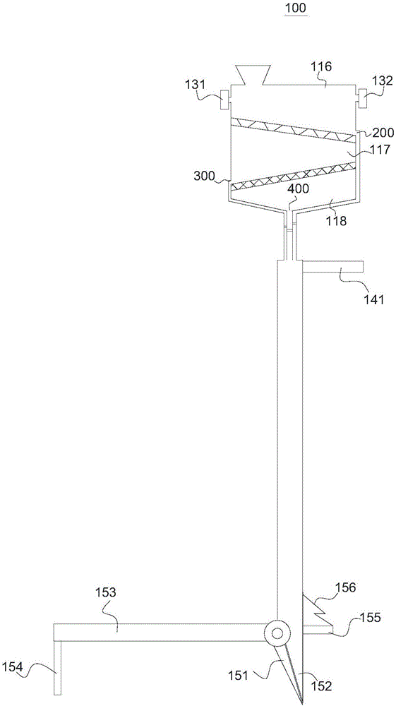
[0052] Example 2, see Figure 4 as shown,
[0053] Seeder 500, its implementation principle and technical effects are the same as those in Embodiment 1. For brief description, for the parts not mentioned in this embodiment, you can refer to the corresponding content in Embodiment 1.
[0054] The seeder 100 obtained through the above design can basically solve the problem of single function, simple design structure and easy operation, but in order to further improve its function, the designer further improved the seeder 100 .
[0055] see Figure 4 , as shown in the figure, the first discharge port 200 is connected to the seeding pipe 140, the second discharge port 300 is connected to the seeding pipe 140 through the second pipeline 510, and the second pipeline 510 includes a first section 511 and a second section connected to each other. Section 512, the port of the first section 511 away from the second section 512 communicates with the first discharge port 200 or the secon...
PUM
Abstract
The invention relates to the technical field of agricultural machinery and provides a seeder and a seeding device. The seeder comprises a shell body, a feeding part and a discharging part, a first-grade sieve plate, a second-grade sieve plate, an air blower and a dust collection device, a seeding pipe and a dibbling nozzle, wherein the feeding part and the discharging part are arranged in the shell body; the shell body is internally provided with a feeding chamber, a first sieving chamber and a second sieving chamber; the discharging part is provided with a first discharging hole, a second discharging hole and a third discharging hole which are communicated with the feeding chamber, the first sieving chamber and the second sieving chamber in sequence; the first-grade sieve plate and the second-grade sieve plate are obliquely arranged in the shell body; the air blower and the dust collection device are located in the feeding chamber; the seeding pipe is selectively communicated with the first discharging hole, the second discharging hole and the third discharging hole; the dibbling nozzle is arranged at an outlet end of the seeding pipe and comprises a fixed shovel and a movable shovel which are movably connected. According to the seeder provided by the invention, seed impurity removal, sieving and selective seeding can be realized at the same time. The seeding device comprises the seeder and a sprinkler connected with the seeder; the seeding device has diversified functions and a scientific design.
Description
technical field [0001] The invention relates to the technical field of agricultural machinery, in particular to a seeder and a seeder. Background technique [0002] The seeder refers to the planting machinery that uses crops and seeds as the sowing objects. The seeder has the characteristics of uniform seeding, consistent depth, stable row spacing, good soil covering, seed saving, and high work efficiency. [0003] However, most of the seeders in the prior art have the disadvantage of single function. Contents of the invention [0004] The object of the present invention is to provide a seeder, which can screen seeds with different particle sizes, and realize seed removal, screening and selective sowing at the same time. [0005] Another object of the present invention is to provide a sowing device, which has the characteristics of various functions and scientific design. [0006] The present invention is achieved like this: [0007] A seeder, comprising: a housing, the...
Claims
Application Information
Patent Timeline
Application Date:The date an application was filed.
Publication Date:The date a patent or application was officially published.
First Publication Date:The earliest publication date of a patent with the same application number.
Issue Date:Publication date of the patent grant document.
PCT Entry Date:The Entry date of PCT National Phase.
Estimated Expiry Date:The statutory expiry date of a patent right according to the Patent Law, and it is the longest term of protection that the patent right can achieve without the termination of the patent right due to other reasons(Term extension factor has been taken into account ).
Invalid Date:Actual expiry date is based on effective date or publication date of legal transaction data of invalid patent.