View-angle-switchable liquid crystal display device and driving method

A technology of a liquid crystal display device and a driving method, which is applied in nonlinear optics, instruments, optics, etc., can solve the problems of afterimage and in-plane display unevenness, and achieves improvement of afterimage and in-plane Mura, image quality improvement, and strong operation. The effect of flexibility and convenience

Active Publication Date: 2017-05-10
KUSN INFOVISION OPTOELECTRONICS
View PDF6 Cites 30 Cited by
  • Summary
  • Abstract
  • Description
  • Claims
  • Application Information

AI Technical Summary

Problems solved by technology

[0009] The object of the present invention is to provide a liquid crystal display device with a switchable viewing angle and a driving method, so as to re

Method used


Image

  • View-angle-switchable liquid crystal display device and driving method
  • View-angle-switchable liquid crystal display device and driving method
  • View-angle-switchable liquid crystal display device and driving method

Examples


no. 1 example

[0038] Figure 4 It is a schematic diagram of the circuit structure of the liquid crystal display device in the first embodiment of the present invention, Figure 5 for Figure 4A schematic cross-sectional view of the liquid crystal display device along the line V-V, Image 6 for Figure 5 Schematic diagram of the structure of a liquid crystal display device at a narrow viewing angle, Figure 7 for Figure 4 A schematic plan view of the viewing angle control electrode of a liquid crystal display device, please refer to Figure 4 to Figure 7 , the liquid crystal display device in this embodiment includes a display panel 20, and the display panel 20 includes a first substrate 21, a second substrate 22 opposite to the first substrate 21, and a substrate between the first substrate 21 and the second substrate 22. Liquid crystal layer 23 . Wherein, the first substrate 21 is a color filter substrate, and the second substrate 22 is a thin film transistor array substrate.

[00...

no. 2 example

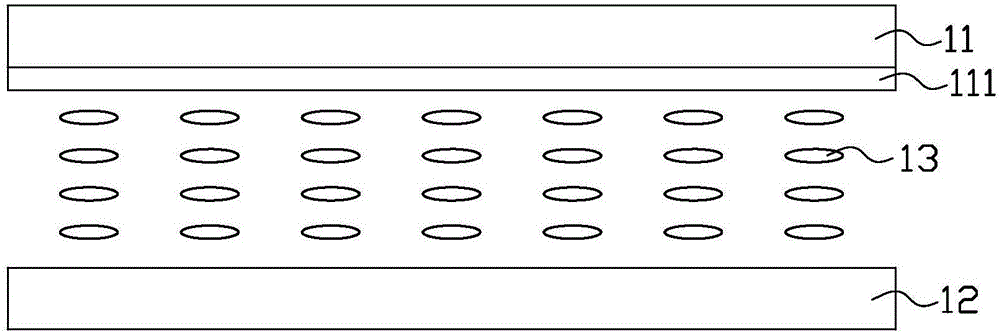
[0077] Figure 11 It is a schematic cross-sectional view of a liquid crystal display device at a wide viewing angle in the second embodiment of the present invention, Figure 12 for Figure 11 Schematic diagram of the cross-section of a liquid crystal display device at a narrow viewing angle, please refer to Figure 11 and Figure 12 The difference between this embodiment and the first embodiment above is that the liquid crystal layer 23 in this embodiment uses negative liquid crystal molecules. In the initial state (that is, when no voltage is applied to the display panel 20), the negative liquid crystal molecules in the liquid crystal layer 23 have an initial pretilt angle relative to the substrates 21, 22, that is, the negative liquid crystal molecules are inclined relative to the substrates 21, 22. posture (eg Figure 11 ).

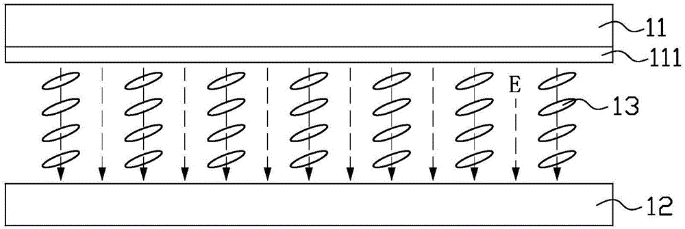
[0078] Please refer to Figure 11 , when the same DC voltage signal as the DC common voltage signal (DC Vcom) of the common electrode 226 is ap...


PUM


Abstract

Provided are a view-angle-switchable liquid crystal display device and a driving method. The liquid crystal display device comprises a display panel, the display panel comprises a first substrate, a second substrate opposite to the first substrate, and a liquid crystal layer located between the first substrate and the second substrate. A view angle control electrode is arranged on the first substrate and used for controlling the display panel to be switched between a wide view angle mode and a narrow view angle mode, a plurality of sub-pixels are defined on the second substrate through scanning lines and data lines, and a pixel electrode is arranged in each sub-pixel of the second substrate. A common electrode is further arranged on the second substrate, the view angle control electrode comprises a plurality of insulated and separated view angle control electrode strips, and each view angle control electrode strip extends in the direction parallel to the scanning lines and corresponds to a row of sub-pixels. According to the liquid crystal display device and the driving method, the problems about residual shadows and in-face Mura can be effectively relieved, so that the image quality is improved.

Description

technical field [0001] The invention relates to the technical field of liquid crystal display, in particular to a liquid crystal display device and a driving method with a switchable viewing angle. Background technique [0002] Liquid crystal display (liquid crystal dilay, LCD) has the advantages of good image quality, small size, light weight, low driving voltage, low power consumption, no radiation and relatively low manufacturing cost, and occupies a dominant position in the field of flat panel display. [0003] Currently, liquid crystal display devices are gradually developing toward wide viewing angles. For example, liquid crystal display devices using in-plane switching (IPS) or fringe field switching (FFS) modes can achieve wider viewing angles. However, in today's society, people pay more and more attention to protecting their privacy, and there are many things that they don't like to share with others. In public places, I always hope that when I look at my mobile p...

Claims


Application Information

Patent Timeline
IPC IPC(8): G02F1/13G02F1/1343
CPCG02F1/1323G02F1/134309
Inventor 王新刚
Owner KUSN INFOVISION OPTOELECTRONICS
Why Eureka
Try Eureka