Radar repeated-frequency separation method based on pulse time delay matching

A technology of pulse delay and repetition frequency, applied in radio wave measurement systems, instruments, etc., can solve the problems of missing and overreporting, false alarms in repetition frequency sorting, etc., to achieve accurate repetition frequency testing and reduce repetition frequency sorting. The effect of false positives

Inactive Publication Date: 2017-05-17
中国人民解放军63889部队
View PDF5 Cites 13 Cited by
  • Summary
  • Abstract
  • Description
  • Claims
  • Application Information

AI Technical Summary

Problems solved by technology

[0007] The above reasons lead to problems such as false positives, missed negatives and over-reported repeated frequency sorting

Method used


Image

  • Radar repeated-frequency separation method based on pulse time delay matching
  • Radar repeated-frequency separation method based on pulse time delay matching
  • Radar repeated-frequency separation method based on pulse time delay matching

Examples


Embodiment Construction

[0040] The specific implementation manners of the present invention will be described in further detail below in conjunction with the accompanying drawings.

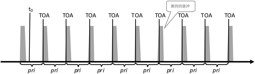
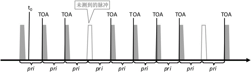
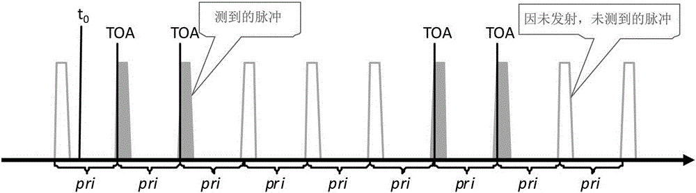
[0041] The technical solution of the present invention is that, because the state of the radiation pulse signal source is relatively stable in a period of time, the radiation source measured by the reconnaissance receiver produces t in the pulse sequence TOA 0 +δ t is a stable constant, defined as the amount of delay, and td is used to represent a random amount. In actual use, the situation of multiple signals with the same carrier frequency, the same repetition frequency, the same pulse width, and the same time delay is very small. Therefore, The pulse sequence can be judged and distinguished according to the pulse delay;

[0042] ①In a measurement period, if n pulses are received, record the arrival time interval of adjacent pulses as:

[0043] pri(k)=toa k -toa k-1 0

[0044] Record the number...


PUM


Abstract

The invention provides a radar repeated-frequency separation method based on pulse time delay matching. The radar repeated-frequency separation method utilizes a separation algorithm, pulse sequence repeated-frequency testing is accurate, and the problems such as misinformation, missed reporting and excessive reporting of repeated-frequency separation in the actual usage process can be decreased.

Description

technical field [0001] The invention relates to radar pulse sorting, in particular to a radar repetition frequency sorting method based on pulse time delay matching. Background technique [0002] For any radiation pulse signal source, its state is relatively stable within a certain period of time without human intervention. Therefore, for any radiation source with a fixed repetition frequency signal pulse sequence, such as figure 1 As shown, ideally, the time-of-arrival TOA of each pulse measured at the reconnaissance receiver must satisfy Equation 1: [0003] TOA(i)=t 0 +pri×i+δ t i = 1, 2, . . . (1) [0004] Among them, t 0 is the initial measurement moment of the pulse sequence, pri is the repetition period (repetition frequency) of the pulse sequence, δ t Pulse arrival time measurement error. [0005] Due to factors such as transmitters, antennas, space environments, and reconnaissance receivers, it is often impossible to accurately measure all TOA facts, that is...

Claims


Application Information

Patent Timeline
Patent Type & Authority Applications(China)
IPC IPC(8): G01S7/285G01S7/40
CPCG01S7/285G01S7/4021
Inventor 刘洪亮赵纲贺天章韩非王在立林东风孙文磊李鹏
Owner 中国人民解放军63889部队
Why Eureka
Try Eureka