Al technical title is built by PatSnap Al team. It summarizes the technical point description of the patent document.
An intelligent electric lock and electric technology, which is applied to electric check locks, non-mechanical transmission-operated locks, building locks, etc., can solve the problems of unreasonable design of intelligent electric lock motors and gearboxes, difficulty in replacing lock cylinders, and large lock sizes. and other problems, to achieve the effect of easy beautification design, compact structure and simplified structure
Inactive Publication Date: 2017-07-21
SHENZHEN GENIUSMART TECH CO LTD
View PDF0 Cites 3 Cited by
Summary
Abstract
Description
Claims
Application Information
AI Technical Summary
This helps you quickly interpret patents by identifying the three key elements:
Problems solved by technology
Method used
Benefits of technology
Problems solved by technology
[0003] The purpose of the embodiment of the present invention is to provide an intelligent electric lock, aiming at solving the problem of large size of the lock caused by the unreasonable design of the motor and gearbox of the existing intelligent electric lock, and the difficulty of replacing the lock cylinder
Method used
Image
Click on the blue label to locate the original text in one second.
Reading with bidirectional positioning of images and text.
Examples
Embodiment Construction
[0015] In order to make the object, technical solution and advantages of the present invention clearer, the present invention will be further described in detail below in conjunction with the accompanying drawings and embodiments. It should be understood that the specific embodiments described here are only used to explain the present invention, not to limit the present invention. In addition, the technical features involved in the various embodiments of the present invention described below can be combined with each other as long as they do not constitute a conflict with each other.
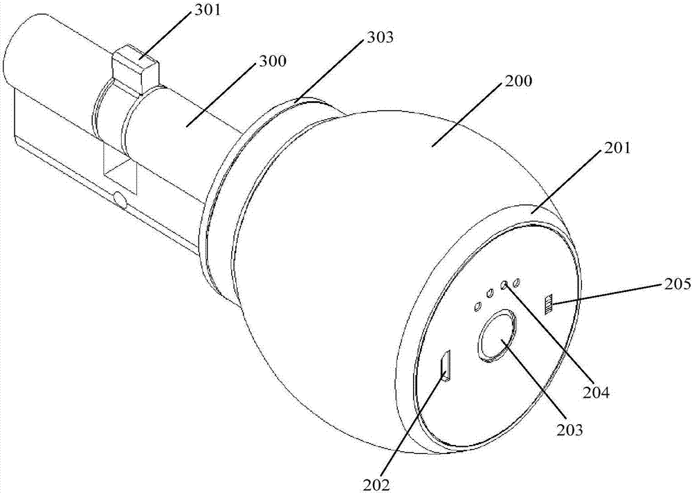
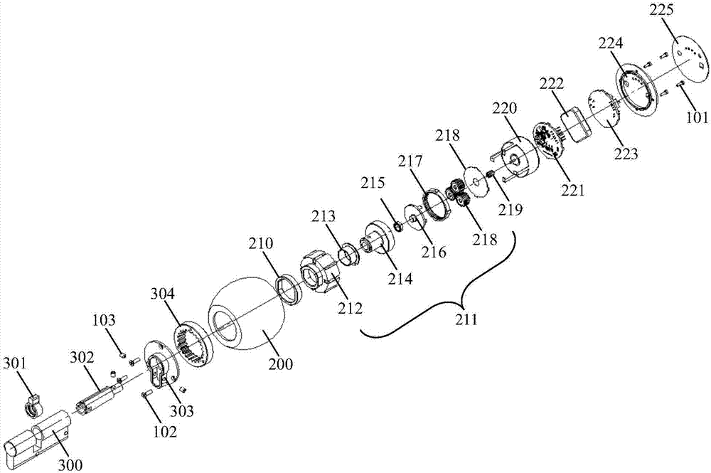
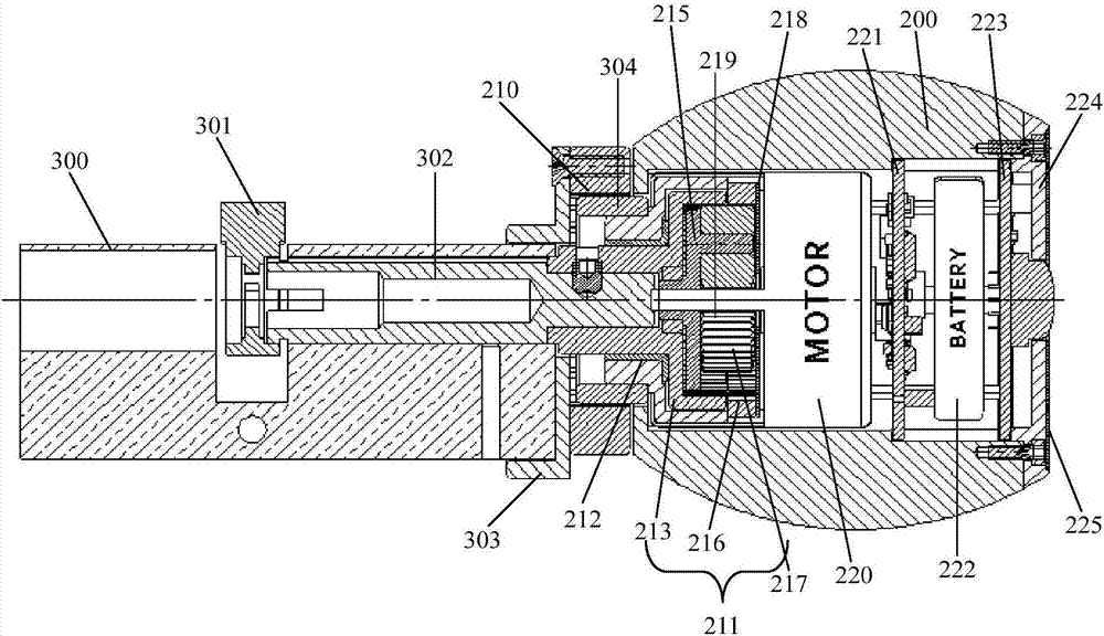
[0016] In the embodiment of the present invention, the motor, gear box, motor drive board, battery, and control board are designed in a coaxial multi-layer integration, and installed in the indoor electric handle of the intelligent electric lock, which improves the overall integration of the intelligent electric lock, reduces the The size of the lock is reduced; and the installation structure si...
PUM
Abstract
The present invention is applicable to the field of electric locks, and provides an intelligent electric lock, which includes a general outdoor key handle, an indoor electric handle and a lock core, a lock tongue, a lock core shaft, a lock core support plate and an end cover, and a lock core There is a magnetic ring on the support plate, and the indoor electric handle includes a coaxial multi-layer integrated structure in sequence along the central axis from the direction of the lock cylinder support plate to the direction of the end cover: permanent magnet ring, gear box, sliding bearing , output internal gear, rolling bearing, planetary wheel turret, fixed internal gear, planetary wheel, gasket, motor pinion, motor, motor drive board, battery and control board; charging interface and quick release button are set on the end cover; lock cylinder It has a general installation structure size. In the present invention, the motor, gear box, motor drive board, battery, and control board are designed in a coaxial multi-layer integration, which improves the overall integration of the lock and reduces the size of the lock; and the installation structure size of the lock cylinder is different from that of the traditional lock. Universal, easy to replace the lock cylinder.
Description
technical field [0001] The invention belongs to the field of electric locks, in particular to an intelligent electric lock. Background technique [0002] With the improvement of the automation level of people's production and life, the application of intelligent electric locks is becoming more and more widespread. However, due to the unreasonable design of the motor and gearbox part of the previous intelligent electric locks, the size is large and the shape is special, which affects the overall appearance of the lock. And it is also very difficult to replace and install the lock cylinder on the general lockset, which has seriously affected the popularization and use of the original intelligent lock cylinder. Contents of the invention [0003] The purpose of the embodiment of the present invention is to provide an intelligent electric lock, aiming at solving the problem of large size of the lock due to the unreasonable design of the motor and the gearbox of the existing int...
Claims
Application Information
Patent Timeline
Application Date:The date an application was filed.
Publication Date:The date a patent or application was officially published.
First Publication Date:The earliest publication date of a patent with the same application number.
Issue Date:Publication date of the patent grant document.
PCT Entry Date:The Entry date of PCT National Phase.
Estimated Expiry Date:The statutory expiry date of a patent right according to the Patent Law, and it is the longest term of protection that the patent right can achieve without the termination of the patent right due to other reasons(Term extension factor has been taken into account ).
Invalid Date:Actual expiry date is based on effective date or publication date of legal transaction data of invalid patent.