Projector calibration method and apparatus

A projector and projection technology, which is applied in the direction of instruments, image data processing, calculation, etc., can solve the problems of low accuracy and low efficiency of the calibration process

Active Publication Date: 2017-07-28
ゼジャンハーレイテクノロジーカンパニーリミテッド
View PDF5 Cites 9 Cited by
  • Summary
  • Abstract
  • Description
  • Claims
  • Application Information

AI Technical Summary

Problems solved by technology

[0005] The present invention provides a method and device for calibrating a projector, which are used to solve the problems in the prior art that the accuracy of the calibrating result of the projector is low and the efficiency of the calibrating process is low

Method used


Image

  • Projector calibration method and apparatus
  • Projector calibration method and apparatus
  • Projector calibration method and apparatus

Examples


Embodiment 1

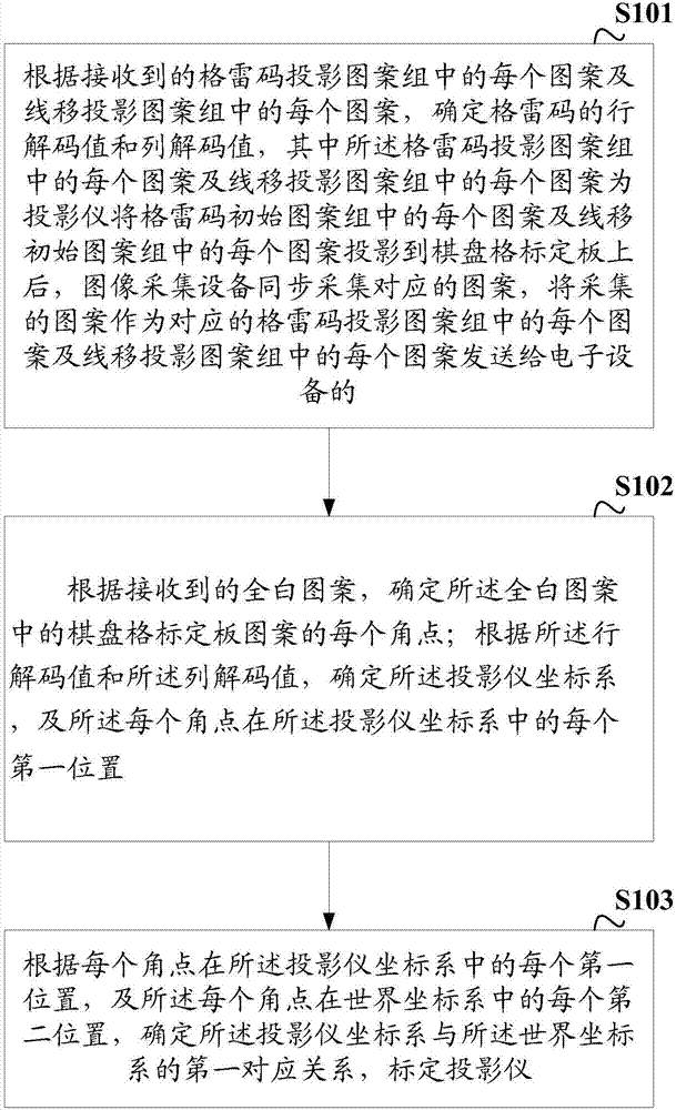
[0058] figure 1 A schematic diagram of a projector calibration method provided by an embodiment of the present invention, the method includes the following steps:

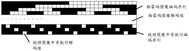
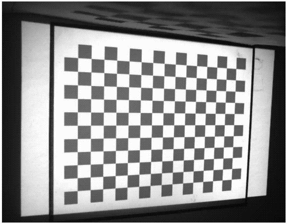
[0059] S101: According to each pattern in the received Gray code projection pattern group and each pattern in the line-shift projection pattern group, determine the row decoding value and column decoding value of the Gray code, wherein the Gray code projection pattern group Each pattern and each pattern in the line-shift projection pattern group is after the projector projects each pattern in the Gray code initial pattern group and each pattern in the line-shift initial pattern group to the checkerboard calibration board, image acquisition The device collects the corresponding pattern, and sends the collected pattern to the electronic device as each pattern in the corresponding Gray code projection pattern group and each pattern in the line shift projection pattern group.

[0060] The projector calibration method ...

Embodiment 2

[0080] The Gray code initial pattern group can be saved in the projector in advance, in order to ensure the consistency of the Gray code initial pattern group in the electronic device and the projector, on the basis of the above-mentioned embodiments, in the embodiment of the present invention, the receiving Gray code Each pattern in the code projection pattern set includes:

[0081] According to the locally saved Gray code pattern generation rules, generate each pattern in the Gray code initial pattern group, wherein each pattern in the Gray code initial pattern group includes a line Gray code initial pattern, a reverse row Gray code initial pattern, Column Gray code initial pattern and reverse column Gray code initial pattern;

[0082] Send each pattern in the gray code initial pattern group to the projector, so that after the projector projects each pattern in the gray code initial pattern group onto the checkerboard calibration board, the image acquisition device synchrono...

Embodiment 3

[0089] In order to further ensure the accuracy of the line decoding value and the decoding value of the Gray code, and improve the calibration efficiency, on the basis of the above-mentioned embodiments, in the embodiment of the present invention, each pattern in the receiving line-shifting projection pattern group includes:

[0090] Delete the even-numbered rows in the row-line-shift initial pattern and the column-line-shift initial pattern according to the row-line-shift initial pattern and column-line-shift initial pattern in the pre-saved line-shift initial pattern group;

[0091] Sending the initial row line shift pattern and column line shift initial pattern after deleting even-numbered rows to the projector, so that the projector projects the row line shift initial pattern and column line shift initial pattern after deleting even-numbered rows onto a checkerboard grid After the plate is calibrated, the image acquisition device collects the corresponding pattern, and send...


PUM


Abstract

The invention discloses a projector calibration method and device for use in electronic equipment. The method comprises the steps of determining a row decoding value and a column decoding value of the Gray code based on each pattern in a received Gray code projection pattern group and each pattern in a line shift projection pattern group; determining each corner point in an all-white checkerboard calibration board pattern based on the received all-white checkerboard calibration board pattern; determining a projector coordinate system and a first position of each corner point in the projector coordinate system based on the row decoding value and the column decoding value; and according to the first position of each corner point in the projector coordinate system and a second position of each corner point in a world coordinate system, determining a corresponding relationship between the projector coordinate system and the world coordinate system, and calibrating the projector. In the projector calibration method provided by the invention, the accuracy of the calibration result is improved while the efficiency of the calibration process is ensured.

Description

technical field [0001] The invention relates to the technical field of structured light three-dimensional measurement, in particular to a projector calibration method and device. Background technique [0002] Structured light three-dimensional measurement technology has the advantages of non-contact, high precision and high speed, and is widely used in scientific analysis, bioengineering, industrial production and other fields. In structured light 3D measurement, there is a 3D measurement system consisting of a single camera and a single projector. This system has a simple structure and high measurement efficiency, but the measurement system involves calibration of the camera and projector. There are relatively mature calibration methods for camera calibration. However, a projector is not an imaging device, but the process of projector projection can be regarded as the reverse process of camera imaging, and the camera needs to be used to calibrate the projector. [0003] In...

Claims


Application Information

Patent Timeline
Patent Type & Authority Applications(China)
IPC IPC(8): G06T7/80
Inventor 高晶晶周璐刘羽
Owner ゼジャンハーレイテクノロジーカンパニーリミテッド
Why Eureka
Try Eureka