Cable cooling device

A cooling device and cable technology, which is applied in the direction of cable/conductor manufacturing, conductor/cable insulation, circuit, etc., can solve the problems of affecting the subsequent process, poor cooling effect, and uneven cooling degree, so as to save process and improve stability , the effect of uniform wind

Inactive Publication Date: 2017-09-22
山东励仙电力工程有限公司
View PDF6 Cites 7 Cited by
  • Summary
  • Abstract
  • Description
  • Claims
  • Application Information

AI Technical Summary

Problems solved by technology

A U-shaped water tank is usually used to cool the cable. In order to prevent the water in the U-shaped water tank from overflowing, a water-blocking device is usually installed at the end of the U-shaped tank. However, in order to avoid damage to the surface of the cable caused by the water-blocking device, there It is also necessary to set a sufficiently safe gap, which causes the water in the U-shaped tank to overflow from the gap, causing the water level in the U-shaped tank to be insufficient to cover the cables, resulting in poor cooling effect and uneven cooling degree
In addition, too much moisture remains on the surface of the cable, which affects the subsequent process

Method used


Image

  • Cable cooling device
  • Cable cooling device
  • Cable cooling device

Examples


Embodiment 1

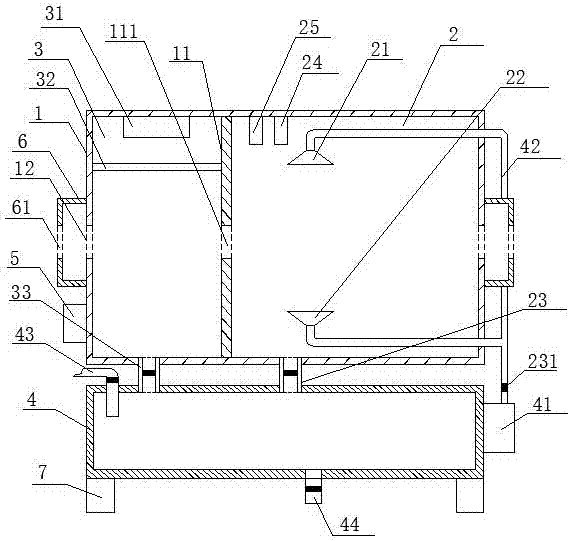
[0040] see Figure 1~3 , a cable cooling device, comprising a cooling box 1, the middle part of the left and right side walls of the cooling box 1 is respectively provided with openings 12, the center lines of the openings 12 coincide, the inner cavity of the cooling box 1 is vertically separated with a partition 11, the right side of the partition 11 is connected to the The inner cavity of the cooling box 1 forms a water-cooling chamber 2, the left side of the partition 11 and the inner cavity of the cooling box 1 form a drying chamber 3, and the center of the partition 11 is provided with a hole 111 whose center line coincides with the opening 12, and the water-cooling chamber 2 passes through the hole 111 It communicates with the drying chamber 3.

[0041] When in use, first put the cable into the right opening 12 of the cooling box 1 and pass through the opening 12 on the left, so that the cable passes through the cooling box 1, the cable continues to move from left to rig...

Embodiment 2

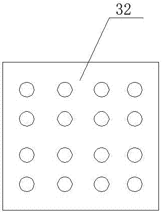
[0059] The difference between embodiment 2 and embodiment 1 lies in the structure of the diffuser plate, specifically, see Figure 4 , the diffuser plate 32 includes a frame 321 and a plurality of connecting plates 322, the connecting plates 322 are arranged in the frame 321 and arranged in a criss-cross pattern, the outer wall of the frame 321 is fixedly connected to the inner wall of the drying chamber 3, and the horizontal height of the diffuser plate 32 is greater than the opening 12 level height.


PUM


Abstract

The invention discloses a cable cooling device, which relates to the technical field of cable preparation, and comprises a cooling box. Openings are respectively arranged in the middle of the left and right side walls of the cooling box, and the center lines of the openings overlap. The side and the inner cavity of the cooling box form a water-cooled cooling chamber, and the left side of the partition forms a drying chamber with the inner cavity of the cooling box. There is a hole in the center of the partition that coincides with the center line and the opening, and the water-cooled cooling chamber is connected to the drying chamber through the hole. The invention uses water cooling to cool down the temperature of the cable, and then performs drying treatment to remove the residual moisture on the surface of the cable, saves procedures, improves work efficiency, and is easy to operate.

Description

technical field [0001] The invention belongs to the technical field of cable preparation, and in particular relates to a cable cooling device. Background technique [0002] When the cable is extruded for insulation or sheath, because the temperature is very high, it cannot be cooled immediately after the mold is released, but needs to be cooled by cooling water. In the prior art, a cable cooling water tank is usually used to cool the cable to room temperature as much as possible. A U-shaped water tank is usually used to cool the cable. In order to prevent the water in the U-shaped water tank from overflowing, a water blocking device is usually installed at the end of the U-shaped groove. Must be provided with enough safe gap again, this just makes the water in the U-shaped tank overflow from this gap, causes the water level in the U-shaped tank not enough to have not crossed cable, thereby causes poor cooling effect, and the degree of cooling is uneven. In addition, too mu...

Claims


Application Information

Patent Timeline
Patent Type & Authority Applications(China)
IPC IPC(8): H01B13/00H01B13/14H01B13/24H01B13/30
CPCH01B13/0036H01B13/145H01B13/24H01B13/30
Inventor 伍文慧
Owner 山东励仙电力工程有限公司
Why Eureka
Try Eureka