Die with undercut exit structure with bore sidewall

An inner hole and undercut technology, which is applied in the field of molds with an undercut exit structure, can solve the problem of not having broken lines and so on.

Active Publication Date: 2019-09-20
SUZHOU MITAC PRECISION TECH
View PDF12 Cites 0 Cited by
  • Summary
  • Abstract
  • Description
  • Claims
  • Application Information

AI Technical Summary

Problems solved by technology

[0005] Since the inner hole 101 of the product 100 cannot have a folding line after molding, and the undercut 102 must also be withdrawn, so the existing mold cannot achieve this purpose.

Method used


Image

  • Die with undercut exit structure with bore sidewall
  • Die with undercut exit structure with bore sidewall
  • Die with undercut exit structure with bore sidewall

Examples


Embodiment Construction

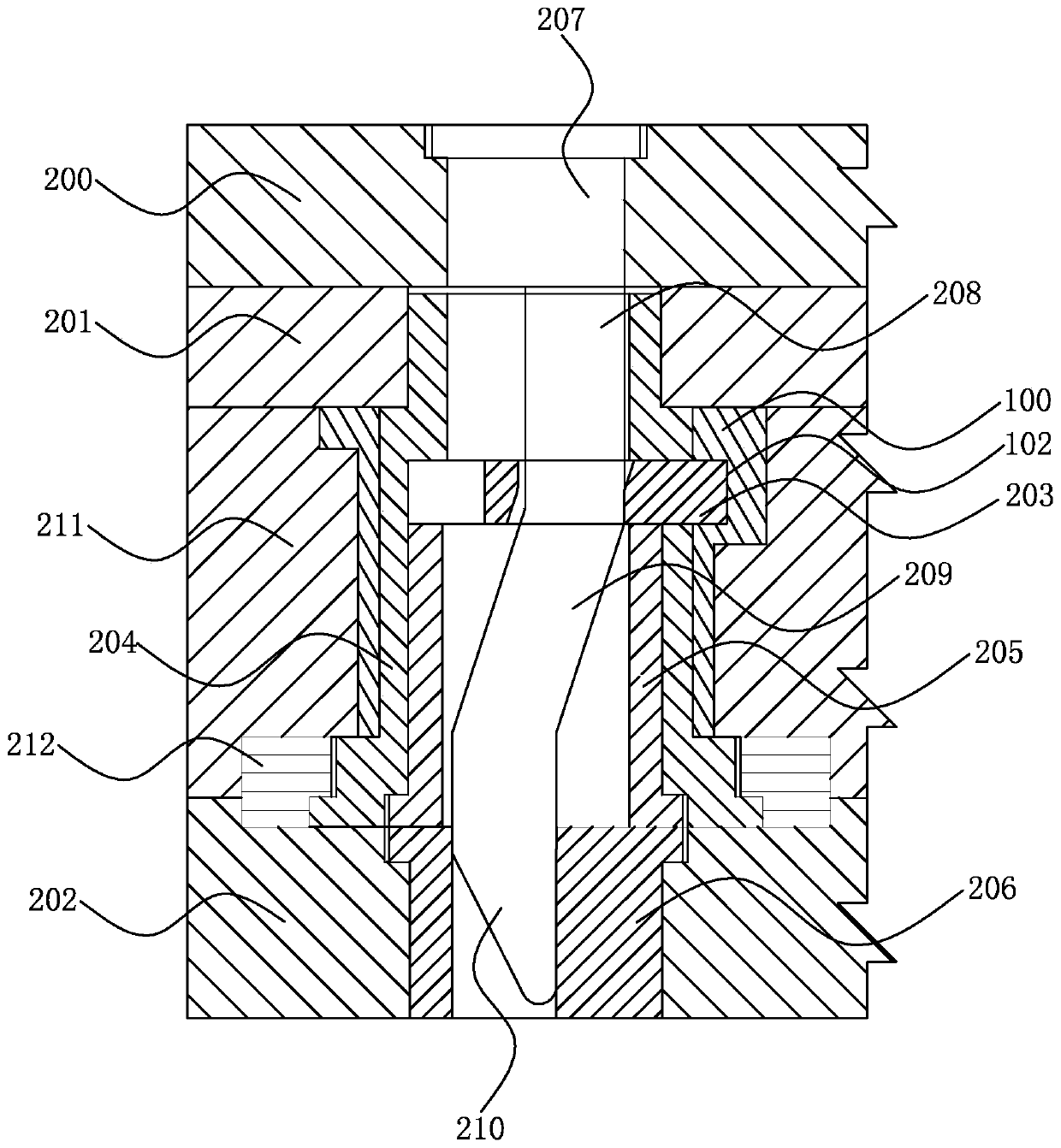
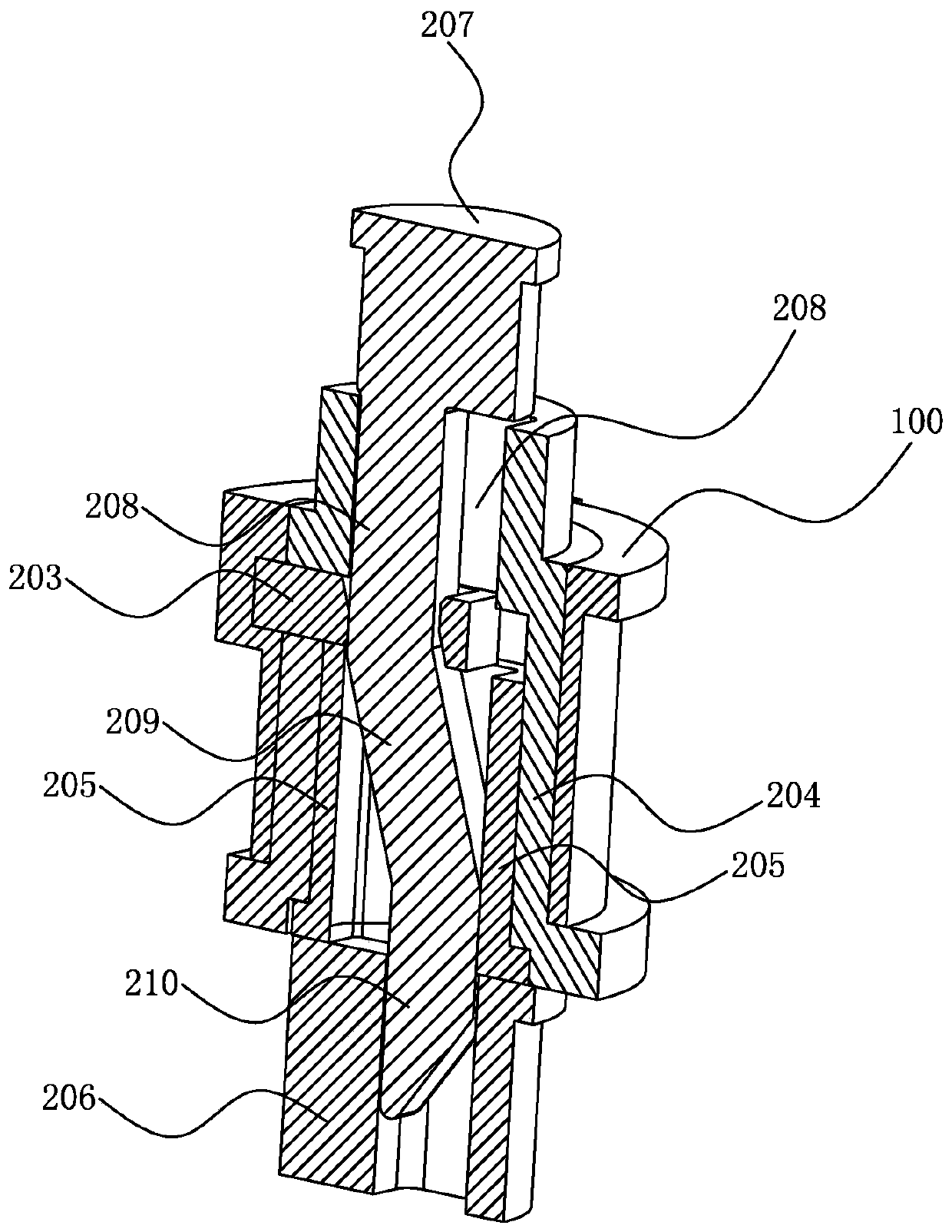
[0028] Please refer to figure 2 , image 3 ,in, figure 2 A schematic cross-sectional structure showing the clamping state of the pull-out push plate structure of the mold of the present invention, image 3 draw figure 2 Schematic diagram of the three-dimensional cross-sectional structure of the middle part of the structure.

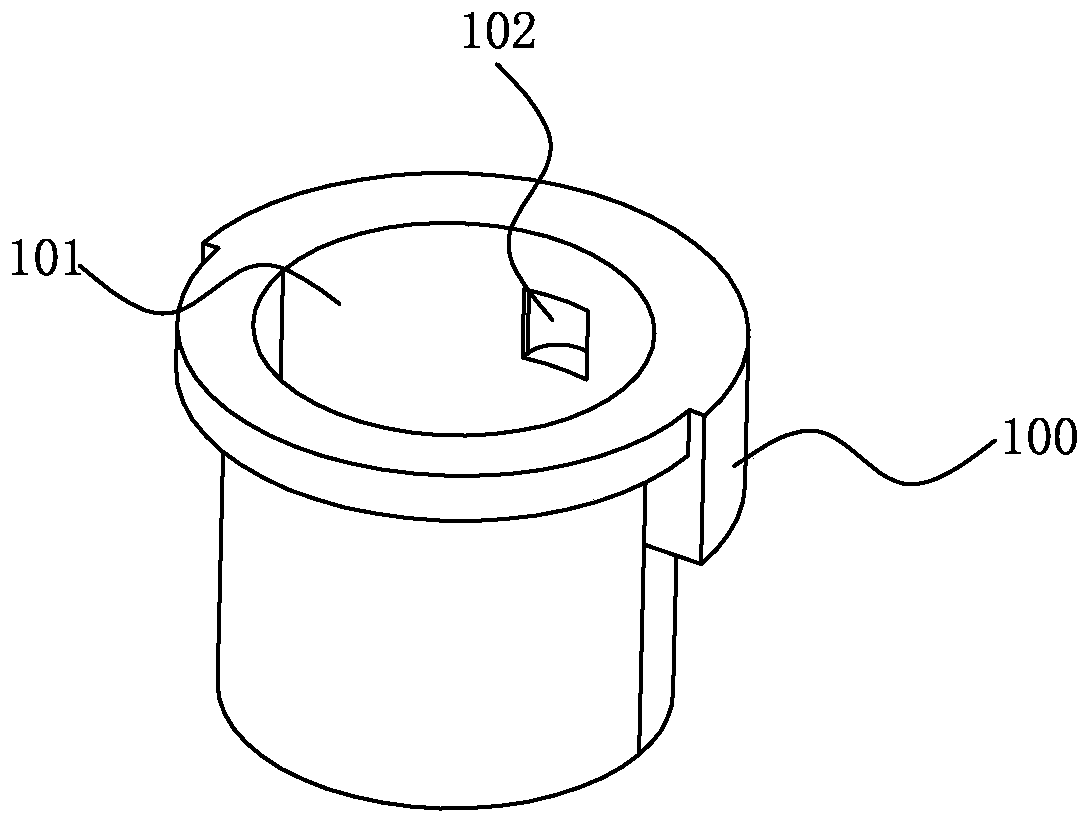
[0029] In order to achieve the above object, the mold of the present invention has an undercut exit structure on the side wall of the inner hole, which molds a product 100 with an undercut 102 on the side wall of the inner hole 101 (please refer to figure 1 ), the mold includes an upper fixed plate 200, a female template 201, a male template (not shown in the figure), and a male mold carrier plate 202 set up in sequence, and the mold also includes:

[0030] Sliding insert 203, one end of which has a forming portion for molding the undercut, and the sliding insert 203 has a sliding through hole;

[0031] The first inlet 204 forms the inner hole 101...


PUM


Abstract

The invention discloses a mold provided with a disengagement structure for an undercut on the side wall of an inner hole. The mold is used for forming a product of which the side wall of the inner hole is provided with the undercut. The mold comprises an upper fixing plate, a female mold plate, a male mold plate and a male mold supporting plate which are arranged in sequence. The mold further comprises a sliding insert, a first insert, a second insert, a third insert and a shifting lever, wherein one end of the sliding insert is provided with a forming part used for forming the undercut, and the sliding insert is provided with a sliding through hole; the first insert is used for forming the inner hole and internally provided with a first through hole, the sliding insert is arranged in the first insert, and the forming part of the sliding insert penetrates out from one side of the first insert; the second insert is sleeved with the first insert, abuts against the lower portion of the sliding insert, and is internally provided with a second through hole; and the third insert is arranged under the second insert and internally provided with a third through hole. The effect that the inner hole of a formed product is free of broken lines, and disengagement of the undercut arranged on the side wall of the inner hole is realized can be achieved.

Description

[0001] 【Technical field】 [0002] The invention relates to a mold structure, in particular to a mold with an undercut exit structure on the side wall of an inner hole. [0003] 【Background technique】 [0004] see figure 1 , figure 1 It is a schematic diagram of the structure of a product. As shown in the figure, the side wall of the inner hole 101 of the product 100 (such as a shaft product) has an undercut 102 . [0005] Since the inner hole 101 of the product 100 cannot have a folding line after molding, and the undercut 102 must be withdrawn, the existing mold cannot be used to achieve this purpose. [0006] In view of this, it is necessary to develop a mold with an undercut exit structure on the side wall of the inner hole to solve the above problems. [0007] 【Content of invention】 [0008] Therefore, the object of the present invention is to provide a mold with an undercut exit structure on the side wall of the inner hole, which can satisfy the requirement that the i...

Claims


Application Information

Patent Timeline
Patent Type & Authority Patents(China)
IPC IPC(8): B29C33/44B22D29/04
Inventor 郭雷
Owner SUZHOU MITAC PRECISION TECH
Why Eureka
Try Eureka