Wire wrapping device for spinning

A winding device and winding technology, which are applied in the directions of transportation and packaging, transportation of filamentous materials, thin material processing, etc., can solve the problems of affecting the winding effect, increase labor costs, and single structure, and improve the smoothness and stability. performance, improve working speed, and improve uniformity

Active Publication Date: 2017-10-03
惠州市骏鹏织造有限公司
View PDF5 Cites 2 Cited by
  • Summary
  • Abstract
  • Description
  • Claims
  • Application Information

AI Technical Summary

Problems solved by technology

[0002] Textile production, processing and manufacturing requires a lot of auxiliary equipment. Auxiliary equipment is also an indispensable tool in production. For example, textile winding machines are one of the most important textile machinery and equipment in modern textile enterprises. Winding machines It is to wind semi-finished products or finished products into a certain form, so as to facilitate storage, transportation and processing in the next process. The current winding equipment generally has a single structure, poor functionality, and is not convenient for users to use, causing great harm to users. It is difficult, and it will lead to uneven winding during winding, which will affect the good winding effect. In the prior art, manual adjustment is generally used, which increases labor costs and improves economic costs.

Method used


Image

  • Wire wrapping device for spinning
  • Wire wrapping device for spinning
  • Wire wrapping device for spinning

Examples


Embodiment Construction

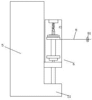
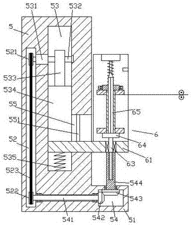
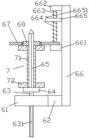
[0022] like Figure 1-Figure 6 As shown in the figure, a textile winding device of the present invention includes a body 5 and a guide transmission wheel 81 arranged on the right side of the body 5 and arranged symmetrically up and down, and the bottom of the end face on the right side of the body 5 is provided with a boss portion 51. A winding mechanism 6 is arranged above the boss portion 51, and the winding mechanism 6 includes a bottom plate 61 extending from left to right, a connecting block 62 fixed on the right rear side of the bottom plate 61, and a connecting block 62 fixed on the connecting plate 61. A straight plate 66 extending upwards at the rear end of the block 62 and a winding base 64 arranged above the bottom plate 61 . The bottom of the first rotating shaft 63 is fixedly provided with an external spline shaft 631 extending downward, and the top of the winding base 64 is fixedly provided with a single key shaft 65. A first transmission cavity 54 is arranged i...


PUM


Abstract

The invention discloses a wire wrapping device for spinning. The wire wrapping device comprises a machine body and guide transmission wheels which are arranged at the right side of the machine body and are symmetrically arranged up and down, wherein a lug boss part is arranged on the bottom of the end surface at the right side of the machine body; a wire wrapping mechanism is arranged above the lug boss part; the wire wrapping mechanism comprises a bottom plate which extends left and right, a connecting block which is fixedly arranged at the rear side of the right side of the bottom plate, a straight plate which is fixedly arranged at the rear side end of the connecting block and extends upwards, and a wire wrapping base arranged above the bottom plate; the bottom of the wire wrapping base is fixedly equipped with a first rotary shaft; the bottom of the first rotary shaft penetrates through the bottom plate and is rotatably connected with the bottom plate in a matched mode; the bottom of the first rotary shaft is fixedly equipped with an outer spline shaft which extends downwards; a single spline shaft is fixedly arranged on the top of the wire wrapping base; a first transmission cavity is arranged in the lug boss part; and an inner spline rotary shaft which extends towards upper and lower sides is rotatably matched and connected in the top wall in the first transmission cavity. The wire wrapping device is simple in structure, realizes automatically controlling upper and lower movable wire wrapping work, improves wire wrapping uniformity, realizes quickly dismounting a bobbin and improves wire wrapping stability.

Description

technical field [0001] The invention relates to the technical field of textile machinery, in particular to a winding device for textiles. Background technique [0002] Textile production requires a lot of auxiliary equipment, and auxiliary equipment is also an indispensable tool in production. For example, textile winding machine, which is one of the most important textile machinery and equipment in modern textile enterprises, winding machine It is to wind semi-finished products or finished products into a certain form to facilitate storage, transportation and processing in the next process. The current winding equipment is generally single in structure, poor in functionality, inconvenient for users to use, and causes great harm to users. In addition, it will cause uneven winding during winding, which affects the good winding effect. The prior art generally adopts manual adjustment, which increases labor expenditure and economic cost. SUMMARY OF THE INVENTION [0003] The...

Claims


Application Information

Patent Timeline
Patent Type & Authority Applications(China)
IPC IPC(8): B65H54/44B65H54/54B65H54/28B65H67/04B65H57/14
CPCB65H54/2803B65H54/44B65H54/543B65H57/14B65H67/0411B65H2701/31
Inventor 冯斌斌
Owner 惠州市骏鹏织造有限公司
Why Eureka
Try Eureka