

Switch cabinet
A technology for switch cabinets and cabinets, which is applied in the direction of switchgear components and power devices inside the switch. It can solve the problems of large starting load, increased motor starting load, and large motor loss, and achieves the effect of improving oil pressure resistance.
- Summary
- Abstract
- Description
- Claims
- Application Information
AI Technical Summary
Problems solved by technology
Method used
Image


Examples
Embodiment Construction
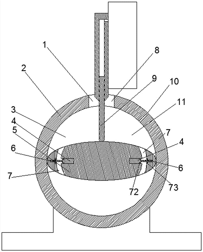
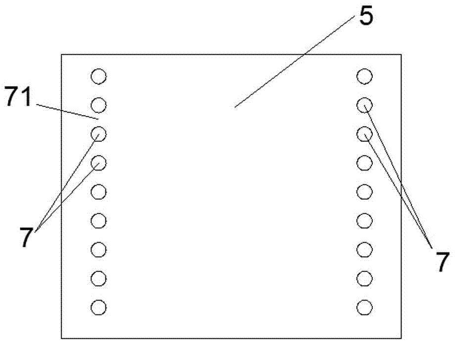
[0020] Examples of switchgear are Figure 1~9 Shown: The switchgear includes a cabinet body, and there are three single-phase units in the cabinet. Each single-phase unit includes a moving contact, a static contact, and a hydraulic operating mechanism that drives the moving contact. The hydraulic operating mechanism includes a power The power part includes a motor 37 and a pump 36, and the execution part includes a hydraulic cylinder and an energy storage spring. The basic working principle is that the power part can pump oil into the hydraulic cylinder, and the hydraulic cylinder compresses the energy storage spring to store energy. When closing is required, the energy storage spring releases energy, and the piston rod of the hydraulic cylinder drives the moving contact to move toward the static contact to realize the closing operation. The working mechanism of the hydraulic operating mechanism belongs to the prior art and will not be described in detail here. The improvement...
PUM
 Abstract
Description
Claims
Application Information