Pull rod device for facilitating on-orbit maintenance of rolling support assembly

A technology of rolling support and tie rod device, which is applied in transportation and packaging, space navigation equipment, tools, etc., can solve the problems of long time consumption and complicated replacement steps, and achieve the effect of improving efficiency, simplifying actions and shortening time.

Active Publication Date: 2018-01-26
SHANGHAI AEROSPACE SYST ENG INST
View PDF5 Cites 2 Cited by
  • Summary
  • Abstract
  • Description
  • Claims
  • Application Information

AI Technical Summary

Problems solved by technology

[0004] The purpose of the present invention is to provide a tie rod device that is convenient for on-rail maintenance of rolling support components, which solves technical problems such as cumbersome and time-consuming on-rail replacement steps of rolling support components in the prior art

Method used


Image

  • Pull rod device for facilitating on-orbit maintenance of rolling support assembly
  • Pull rod device for facilitating on-orbit maintenance of rolling support assembly
  • Pull rod device for facilitating on-orbit maintenance of rolling support assembly

Examples


Embodiment Construction

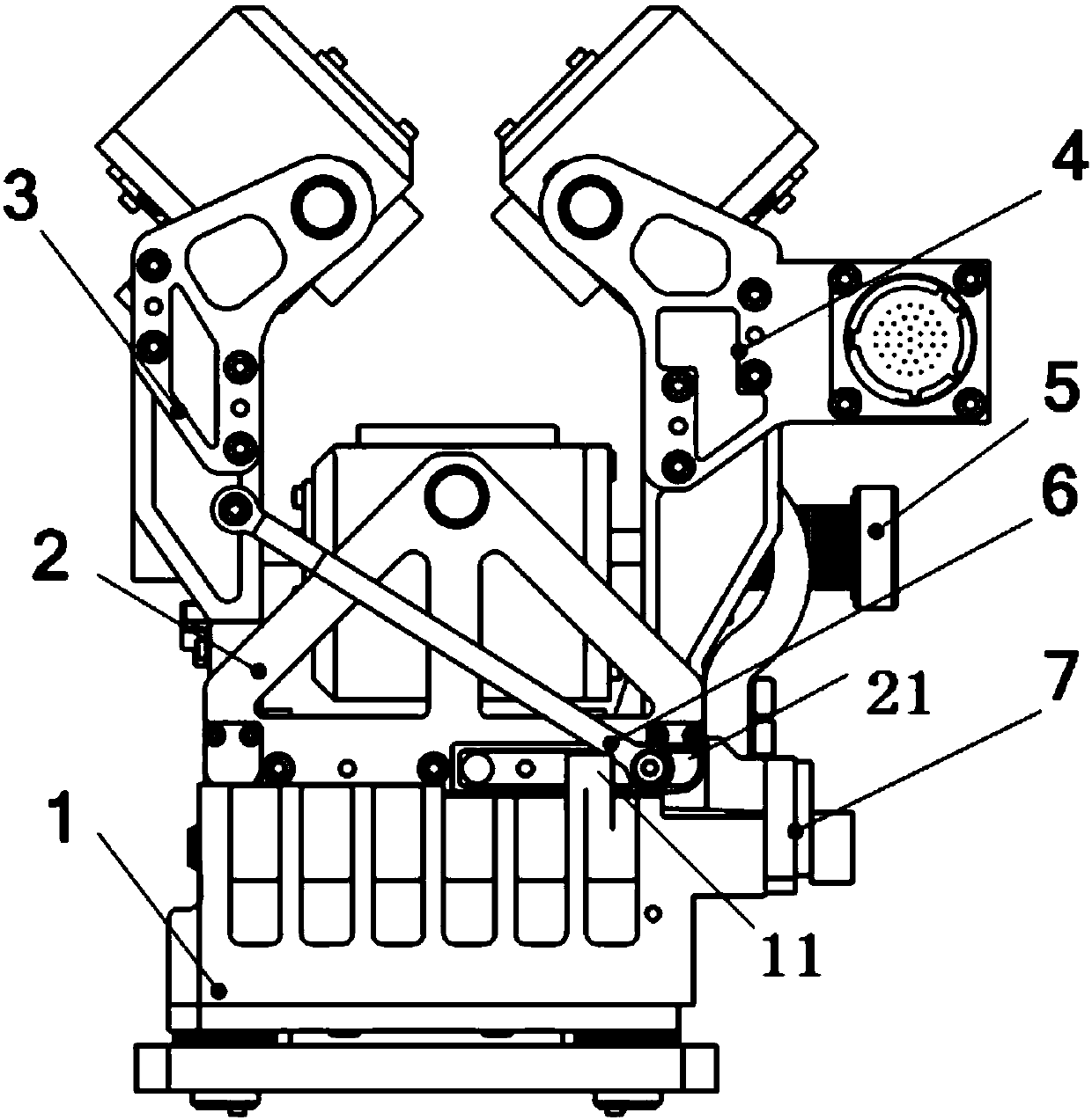
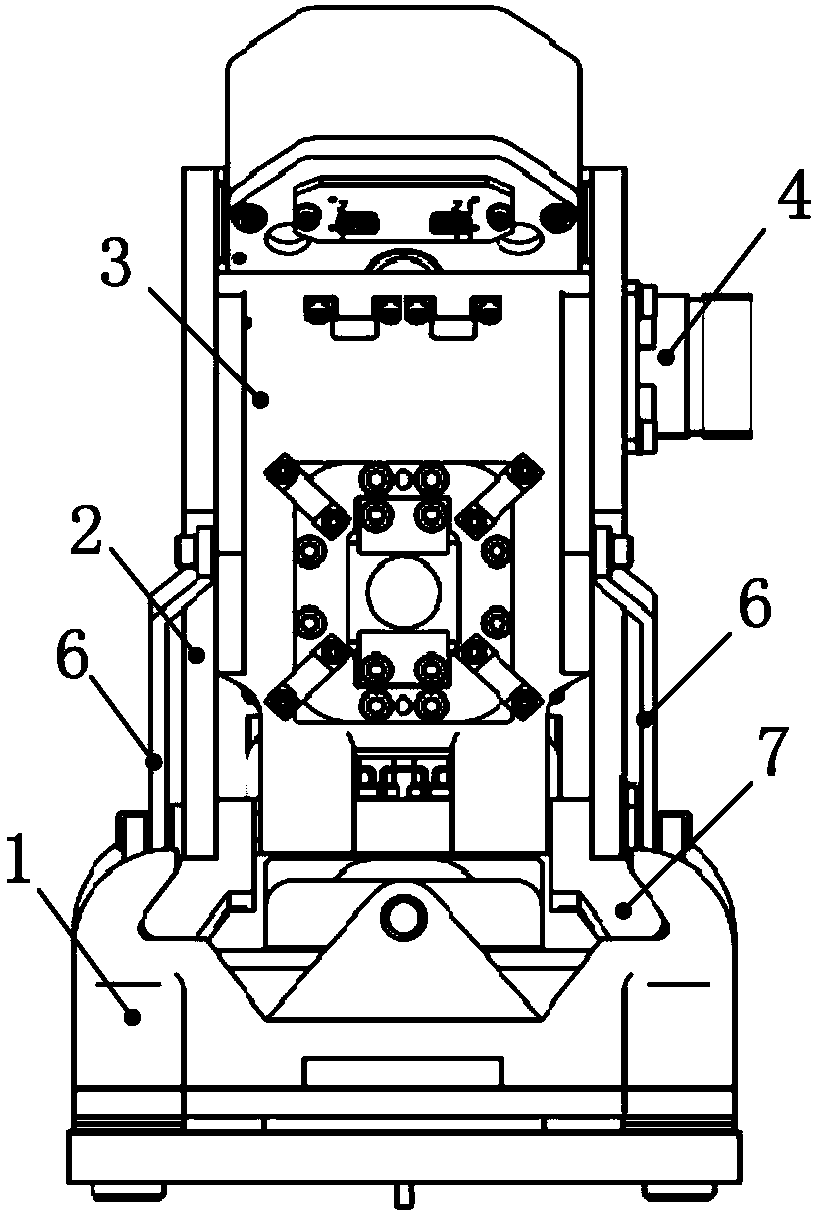
[0029] A specific embodiment will be described in detail below in conjunction with the accompanying drawings.

[0030] Please refer to figure 1 with figure 2 , a pull rod device that facilitates on-rail maintenance of the rolling support assembly. The rolling support assembly includes a clamping device for clamping the rotating guide rail. The clamping device is arranged on a slide table 7, which is slidably connected to the installation On the seat 1, the mounting seat 1 is installed on the sun-orientation device of the space station; the clamping device includes the first clamping arm 3, the second clamping arm 4 and the bottom clamping arm 2, the first clamping arm 3 and the second clamping arm The holding arms 4 are located on both sides of the bottom holding arm 2, the first holding arm 3, the second holding arm 4 and the bottom holding arm 2 are all installed on the slide table 7, and the first holding arm 3 can pass through a The shaft rotation is set on the slide ta...


PUM


Abstract

The invention relates to a pull rod device for facilitating on-orbit maintenance of a rolling support assembly. The rolling support assembly includes a clamping device which is arranged on a sliding table. The sliding table is slidably connected on a mounting base. The rolling support assembly includes a first clamping arm, a second clamping arm and a bottom clamping arm. Both sides of the first clamping arm are rotatably connected with the bottom clamping arm through a pull rod device. The pull rod device comprises a pull rod. An end A of the pull rod is rotatably connected with the first clamping arm, and an end B is connected with the bottom clamping arm in a slidable and rotatable manner. The mounting base is provided with a projection thereon. During on-orbit mounting, the sliding table slides slowly towards the mounting base, the angle between the first clamping arm and the sliding table is large and remains unchanged, when the end B of the pull rod is against the projection, theend B slides on the bottom clamping arm, as the sliding table continues to slide, the pull rod gradually lifts the first clamping arm and the angle between the first clamping arm and the sliding table gradually becomes smaller. The technical problem of tedious on-orbit replacement steps, long time consumption and the like of the rolling support component in the prior art are solved.

Description

technical field [0001] The invention relates to a device for improving the on-rail maintainability of a rolling support assembly, in particular to a pull rod device for facilitating the on-rail maintenance of the rolling support assembly. Background technique [0002] The slewing support mechanism is used in the sun orientation device of the space station. It includes a rolling support assembly and a rotating guide rail. The rolling support assembly is used to clamp and support the rotating guide rail to ensure the continuous and stable rotation of the solar wing. First of all, the rolling support assembly is a component with the same lifespan as the space station. It needs to continue to operate in orbit for many years. Once it fails, it will directly affect the normal operation of the space station. Therefore, the researchers designed the rolling support assembly to be detachable on-orbit. In the prior art, the rolling support components on the International Space Station ...

Claims


Application Information

Patent Timeline
Patent Type & Authority Applications(China)
IPC IPC(8): B64G4/00
Inventor 马志飞王华马超杨德财钱志源王治易马季军
Owner SHANGHAI AEROSPACE SYST ENG INST
Why Eureka
Try Eureka