Low-pressure testing table for oxygen bottle regulators

A technology of regulators and test benches, which is applied in the direction of container filling methods, container discharge methods, gas/liquid distribution and storage, etc. It can solve the problems of inaccurate adjustment of output gas pressure and inability to detect the performance of control valves, etc., to achieve detection Full range of effects

Pending Publication Date: 2018-02-09
四川奥特附件维修有限责任公司
View PDF6 Cites 2 Cited by
  • Summary
  • Abstract
  • Description
  • Claims
  • Application Information

AI Technical Summary

Problems solved by technology

[0003] The object of the present invention is to provide a low-pressure test bench for oxygen cylinder regulators whose models are P / N: 4441009-XX, 8013207-XX, 807434 / 9700 / 9800XX, 5500-5600XXX and 3552XX, respectively. It is used to solve the problems that the oxygen regulator in the prior art cannot accurately adjust the output gas pressure and cannot detect the performance of the control valve

Method used


Image

  • Low-pressure testing table for oxygen bottle regulators
  • Low-pressure testing table for oxygen bottle regulators

Examples


Embodiment 1

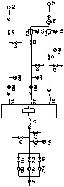
[0038] combined with figure 1 and figure 2As shown, a low-pressure test bench for an oxygen cylinder regulator includes a gas source inlet X5, a vacuum source inlet X6, and an exhaust port X7. One branch and the second branch, the output end of the first branch and the output end of the second branch are respectively provided with the inlet port X1 of the tested part and the inlet port X2 of the tested part, and the inlet of the vacuum source X6 is connected with a third branch for providing a vacuum source to the tested part, the output end of the third branch is provided with the air inlet port X3 of the tested part, and the exhaust port X7 is connected with an output branch. The input end of the output branch is provided with the air outlet interface X4 of the tested piece, and the air inlet interface X1 of the tested piece, the air inlet interface X2 of the tested piece and the air inlet interface X3 of the tested piece are respectively connected to the air inlet port of...

Embodiment 2

[0042] On the basis of Example 1, in conjunction with the attached figure 1 and figure 2 As shown, a filter M2 for filtering gas impurities is also connected between the gas source inlet X5 and the first branch and the second branch.

[0043] working principle:

[0044] A filter M2 is connected between the gas source inlet X5 and the first branch and the second branch to filter impurities from the gas entering the first branch and the second branch to avoid clogging of impurities and the display accuracy of the image pressure gauge .

Embodiment 3

[0046] On the basis of embodiment 2, in conjunction with the attached figure 1 and figure 2 As shown, the first branch includes a main pipeline input pressure regulating decompression valve V1 connected to the filter M2, and the main pipeline input pressure regulating decompression valve V1 is connected with the first main pipeline input regulating needle valve K1. At one end, a pressure gauge PP1 is connected between the main pipeline input pressure regulating pressure reducing valve V1 and the first end of the main pipeline input regulating needle valve K1, and the second end of the main pipeline input regulating needle valve K1 is connected to the The air inlet port X1 of the tested part, the main pipe bypass output cut-off valve K2 is connected between the second end of the main pipe input regulating needle valve K1 and the air inlet port X1 of the tested part.

[0047] working principle:

[0048] After the gas passes through the filter M2 to filter impurities from the ...


PUM


Abstract

The invention discloses a low-pressure testing table for oxygen bottle regulators. The low-pressure testing table comprises a gas source inlet X5, a vacuum source inlet X6 and an exhaust opening X7, wherein the gas source inlet X5 is connected with a first branch and a second branch, the output ends of the first branch and the second branch are separately provided with a tested component gas inletconnector X1 and a tested component gas inlet connector X2, the vacuum source inlet X6 is connected with a third branch, the output end of the third branch is provided with a tested component gas inlet connector X3, the exhaust opening X7 is connected with an output branch, the input end of the output branch is provided with a tested component gas outlet connector X4, the tested component gas inlet connector X1, the tested component gas inlet connector X2 and the tested component gas inlet connector X3 are separately connected with the gas inlet end of a tested component, and the tested component gas outlet connector X4 is connected with the gas outlet end of the tested component. The low-pressure testing table is a special testing table. Opening and closing control valves of the gas bottle regulators are independently regulated, flow and pressure on a gauze head on a shell panel are observed, and the performance test of all kinds of gas bottle regulators can be effectively finished.

Description

technical field [0001] The invention relates to the technical field of pressure and flow testing equipment, in particular to a low-pressure testing platform for an oxygen cylinder regulator. Background technique [0002] At present, regulators are widely used in gas delivery pipelines, and their main function is to adjust the higher upstream inlet pressure to a lower outlet pressure to ensure the stability of the downstream output pressure. Oxygen cylinders are usually used in medicine and chemical industry. The safety of the performance of oxygen cylinder regulators may not only affect the quality of gas delivery, but also directly affect the safety of life and industrial manufacturing. Therefore, the performance of oxygen pressure regulators needs to be checked before use. Special testing. In the prior art, the oxygen cylinder regulator mainly reduces the gas pressure to a safe range, but the performance and accuracy of the oxygen cylinder regulator lacks special testing ...

Claims


Application Information

Patent Timeline
IPC IPC(8): F17C13/02
CPCF17C13/025F17C2250/0626
Inventor 王辛旭曹海艳李明坤
Owner 四川奥特附件维修有限责任公司
Why Eureka
Try Eureka