Page holder and page turner

A technology of book pages and friction parts, which is applied in the fields of book page pressing devices and page turning devices

Inactive Publication Date: 2018-03-16
CASIO COMPUTER CO LTD
View PDF9 Cites 4 Cited by
  • Summary
  • Abstract
  • Description
  • Claims
  • Application Information

AI Technical Summary

Problems solved by technology

[0005] In the above-mentioned prior art, when the impeller rotates, when the blade part collides with the page held at the destination side to be turned, a periodic rattling sound is generated.

Method used


Image

  • Page holder and page turner
  • Page holder and page turner
  • Page holder and page turner

Examples


Embodiment Construction

[0014] Next, the best mode for carrying out the present invention will be described using the drawings. In addition, in the embodiments described below, technically preferable various limitations are made for carrying out the present invention, but the scope of the invention should not be limited to the following embodiments and illustrated examples.

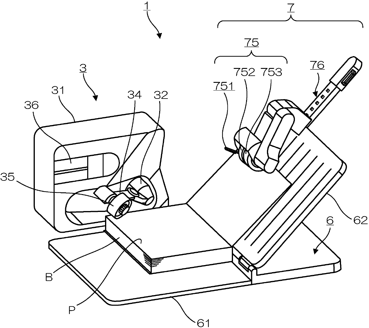
[0015] figure 1 It is a perspective view showing a schematic configuration of the page turning device 1 of the present embodiment. In addition, in the following description, the case where the pages P of the book B are turned from left to right will be described.

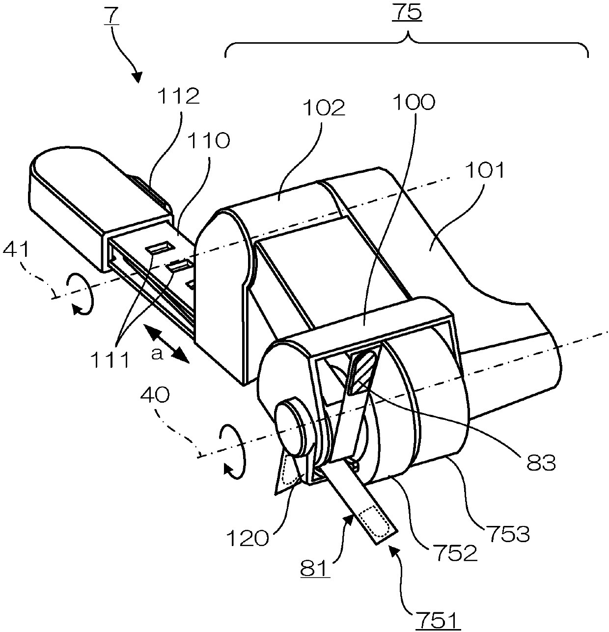
[0016] Such as figure 1 As shown, the page turning device 1 has a page turning unit 3 for turning pages P of a book B, a holder 6 for setting the book B, and a page holding unit 7 for holding the pages P at the turning destination position. In addition, although omitted in the figure, it also has a base part on which an information processing terminal (smartphone, ...


PUM


Abstract

When a page (P) is conveyed from a sticking section, a catching section catches and brings the page (P) to a page-turning end point by a vane section rubbing against a surface of the page. A regulation section is provided extending from a side of a roller cover to an area below vane sections, and regulates the movement of each vane section before a vane section strikes the page (P) already fixed at the page-turning endpoint or strikes a holding plate. By being formed of an elastic member, each vane section is pulled into the roller cover while being greatly bent by the regulation section.

Description

[0001] Cross References to Related Applications [0002] This application is based on and claims priority to Japanese Patent Application No. 2016-177026 for which it applied on September 9, 2016, and the entire content of this basic application is hereby incorporated by reference. technical field [0003] The invention relates to a page pressing device and a page turning device. Background technique [0004] Conventionally, there is known a page-turning device that sucks overlapping book pages one by one to turn the pages (for example, refer to Japanese Patent Application Laid-Open No. 2016-010907 ). The page-turning device has an impeller for introducing the turned-up pages. The impeller is provided with a plurality of blades for rolling in the pages along the circumferential direction. The blade part is formed of a flexible plate-shaped member, and a member having a higher frictional resistance than the book page is provided on the surface of the end part that contacts t...

Claims


Application Information

Patent Timeline
Patent Type & Authority Applications(China)
IPC IPC(8): B42D9/04B42D9/00
CPCB42D9/00B42D9/04B42D9/06A47B23/043A47B23/06H04N1/00602A47B97/02
Inventor 今村尚人
Owner CASIO COMPUTER CO LTD
Why Eureka
Try Eureka