Automatic feeding vehicle for cutting machine

An automatic feeding and cutting machine technology, applied in metal processing and other directions, can solve the problems of easy damage to the work surface, strong work surface pressure, easy damage to rails and rollers, etc. Effect

Inactive Publication Date: 2018-03-30
HONGCHENG SCI & TECH LTD
View PDF0 Cites 3 Cited by
  • Summary
  • Abstract
  • Description
  • Claims
  • Application Information

AI Technical Summary

Problems solved by technology

In order to keep the operator as far away from the cutting machine as possible when operating the cutting machine, an automatic feeding car is used for feeding in the actual production process. The self-feeding car generally uses a motor or a cylinder to push the pallet to move on the track, and the track is placed on the cutting machine. On the table, after the supporting plate is pushed into the cutting machine, the lower platen presses down, and the tool touches the material on the mold. The supporting plate replaces the working table as a part under pressure. The rollers are under pressure, causing the track and rollers to be easily damaged and need to be replaced frequently
Moreover, the contact area between the track and the worktable is small, resulting in high pressure at some positions on the worktable, and the worktable is also easily damaged

Method used


Image

  • Automatic feeding vehicle for cutting machine
  • Automatic feeding vehicle for cutting machine
  • Automatic feeding vehicle for cutting machine

Examples


Embodiment Construction

[0016] The present invention will be further explained below in conjunction with the accompanying drawings and specific embodiments. It should be understood that the following specific embodiments are only used to illustrate the present invention and are not intended to limit the scope of the present invention. It should be noted that the words "front", "rear", "left", "right", "upper" and "lower" used in the following description refer to the directions in the drawings, and the words "inner" and "outer ” refer to directions towards or away from the geometric center of a particular part, respectively.

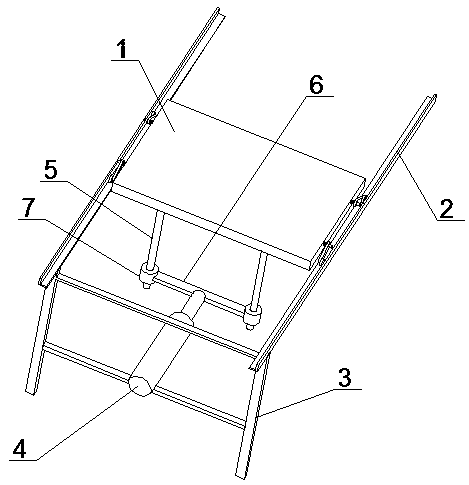
[0017] Such as figure 1 Shown is an automatic feeding car for a cutting machine, including a pallet 1, a track 2, a bracket 3 and a cylinder 4, two tracks 2 are set up in parallel, one end of the track 2 is connected by a bracket 3, and the other end of the track 2 can be placed on the cutting machine. On the working table of the machine, the pallet 1 is placed between the rai...


PUM


Abstract

The invention discloses an automatic feeding vehicle for a cutting machine, which includes a supporting plate, a track, a bracket and a cylinder. The supporting board is placed between the rails, the width of the supporting board is smaller than the opening distance between the rails, the two sides of the supporting board are symmetrically arranged with shafts, each side is provided with two shafts, the shaft is movably connected with a rocker arm, and the other end of the rocker arm is connected There are rollers, and the rollers can roll on the track. A torsion spring is also arranged between the supporting plate and the rocker arm. A cylinder is arranged on the support. The top of the telescopic rod of the cylinder is connected with a push rod, and connecting rings are arranged at both ends of the push rod. , two positioning rods perpendicular to the supporting plate are also arranged on the supporting plate, which are movably connected with the connecting ring. When the feeding trolley is pressed down by the lower platen, the supporting plate contacts the work surface, so that the pressure is evenly distributed, the work surface is not easy to damage, and the track and rollers of the feed trolley are not pressure-bearing parts, which are not easy to damage and do not need to be replaced frequently.

Description

technical field [0001] The invention belongs to the technical field of cutting machine equipment, in particular to an automatic feeding vehicle for a cutting machine. Background technique [0002] Cutting machine is an indispensable equipment in some light industries. It is a machine that uses the force of machine movement to pressurize the die to punch non-metallic materials. When the plane cutting machine is working, it is strictly forbidden for the operator to place his hand on the work surface to prevent the lower platen from pressing the operator's hand. In order to keep the operator as far away from the cutting machine as possible when operating the cutting machine, an automatic feeding car is used for feeding in the actual production process. The self-feeding car generally uses a motor or a cylinder to push the pallet to move on the track, and the track is placed on the cutting machine. On the table, after the supporting plate is pushed into the cutting machine, the ...

Claims


Application Information

Patent Timeline
Patent Type & Authority Applications(China)
IPC IPC(8): B26D7/06
CPCB26D7/0616
Inventor 郭宏兵程春良程永胜郭澍
Owner HONGCHENG SCI & TECH LTD
Why Eureka
Try Eureka