Continuously adjustable throttle valve

A throttling valve and flow adjustment technology, which is applied in valve details, diaphragm valves, valve devices, etc., can solve the problems of inability to accurately control the flow rate, shorten the practical life, sudden changes in flow rate and pressure difference, etc., to ensure that The effect of using, ensuring fluency, and ensuring the effect of flow

Pending Publication Date: 2018-04-06
荣成市固废综合处理与应用产业园有限公司
View PDF0 Cites 0 Cited by
  • Summary
  • Abstract
  • Description
  • Claims
  • Application Information

AI Technical Summary

Problems solved by technology

[0002] As we all know, a throttle valve is a valve that controls fluid flow by changing the throttle area or throttle length. The throttle valve in the prior art generally includes a valve body, a valve core and a regulating rod. The valve core is set in the valve body, and the adjusting rod is used to adjust the position of the valve core in the valve body, so as to adjust the liquid flow in the valve body. The general change process of the existing throttle valve is In the process, the flow and pressure difference changes abruptly, which will generate pressure on the throttle valve, and the practical life will be shortened, and the flow control is generally realized by adjusting the spool and the adjusting rod, and the use of the flow cannot be precisely controlled.

Method used


Image

  • Continuously adjustable throttle valve
  • Continuously adjustable throttle valve
  • Continuously adjustable throttle valve

Examples


Embodiment Construction

[0015] Below in conjunction with accompanying drawing, the present invention is further described:

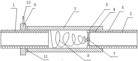
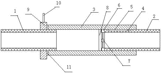
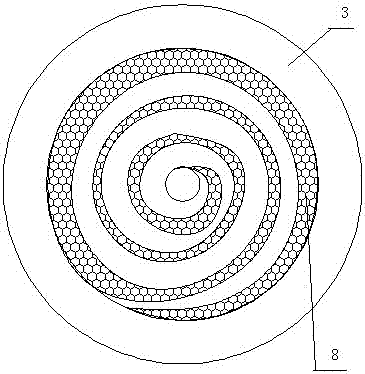
[0016] As shown in the attached figure, a continuously adjustable throttle valve is provided with a water inlet pipe 1 and a water outlet pipe 2. The two ends of the pipe 3 are socketed on the outside of the water inlet pipe 1 and the water outlet pipe 2 with a slight gap. The inner pipe wall connecting the flow regulating pipe 3 and the water outlet pipe 2 is provided with a sliding table 4. The water outlet pipe 2 is provided with a chute 5 matched with the slide table 4, and the two ends of the chute 5 are respectively closed, and the flow regulating pipe 3 slides on the water inlet pipe 1 and the water outlet pipe 2 through the slide table 4 and the chute 5. The end of the water outlet pipe 2 is provided with a baffle, and the baffle is composed of a ring piece 6 and a center piece 7, the ring piece 6 is connected with the center piece 7 through a pole, and the center piece...


PUM


Abstract

The invention relates to the technical field of throttle valve mechanical manufacturing and in particular to a continuously adjustable throttle valve which comprises a water inlet tube and a water outlet tube. The continuously adjustable throttle valve is characterized in that a flow adjusting tube is arranged between the water inlet tube and the water outlet tube; two ends of the flow adjusting tube are connected with the outer sides of the water inlet tube and the water outlet tube in a sleeved manner with a micro gap; a sliding platform is arranged on an inner tube wall connected with the water outlet tube, of the flow adjusting tube; a chute is formed in the water outlet tube; the flow adjusting tube slides on the water inlet tube and the water outlet tube through the sliding platformand the chute; a baffle piece is arranged at the end part of the water outlet tube; the baffle piece consists of an annular piece and a central piece; the annular piece is connected with the central piece through a support rod; a conical spring piece is arranged inside the flow adjusting tube; the opening end of the conical spring piece is arranged at the water inlet end of the flow adjusting tube; and the sharp end of the conical spring piece is connected with the central piece of the baffle piece. The continuously adjustable throttle valve has the advantages of being simple in structure, large in flow adjustment range, smooth in flow pressure difference variation, simple and convenient to operate, and the like.

Description

technical field [0001] The invention relates to the mechanical manufacturing technical field of a throttle valve body, in particular to a continuously adjustable throttle valve with simple structure, large flow adjustment range, smooth flow pressure difference change and easy operation. Background technique [0002] As we all know, a throttle valve is a valve that controls fluid flow by changing the throttle area or throttle length. The throttle valve in the prior art generally includes a valve body, a valve core and a regulating rod. The valve core is set in the valve body, and the adjusting rod is used to adjust the position of the valve core in the valve body, so as to adjust the liquid flow in the valve body. The general change process of the existing throttle valve is In the process, the flow and pressure difference changes abruptly, and pressure is generated on the throttle valve, and the practical life is shortened, and the flow control is generally realized by adjust...

Claims


Application Information

Patent Timeline
IPC IPC(8): F16K7/20F16K31/50F16K27/02
CPCF16K7/20F16K27/0236F16K31/50
Inventor 乔风敏
Owner 荣成市固废综合处理与应用产业园有限公司
Why Eureka
Try Eureka