AI technical title is built by Patsnap AI team. It summarizes the technical point description of the patent document.
A lane line detection and lane line technology, applied in the field of lane line detection, can solve problems such as slow detection speed and cumbersome process, and achieve the effect of improving detection speed and simplifying the process
Active Publication Date: 2018-06-12
INST OF LASER & OPTOELECTRONICS INTELLIGENT MFG WENZHOU UNIV
View PDF5 Cites 7 Cited by
Summary
Abstract
Description
Claims
Application Information
AI Technical Summary
This helps you quickly interpret patents by identifying the three key elements:
Problems solved by technology
Method used
Benefits of technology
Problems solved by technology
[0003] The purpose of the present invention is to provide a simplified method to improve the detection speed of lane lines, and solve the cumbersome process and slow detection speed of the existing lane line detection method based on Hough transform and other defects, it can quickly and accurately obtain lane lines, especially suitable for autonomous navigation of unmanned vehicles and intelligent assisted driving systems of vehicles
Method used
Image
Click on the blue label to locate the original text in one second.
Reading with bidirectional positioning of images and text.
Examples
Embodiment 2
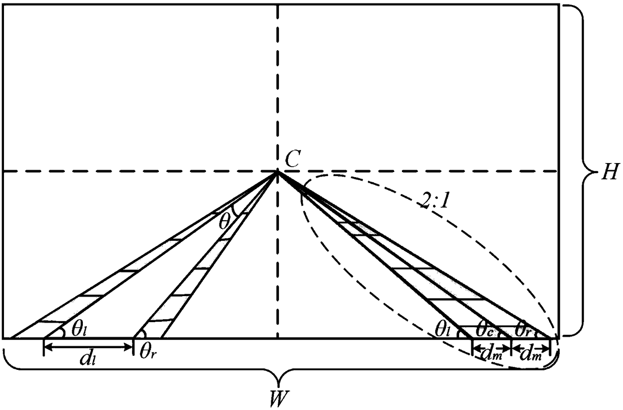
[0053] figure 2 A schematic diagram of the calculation principle of left and right lane lines and lane widths with equal width constraints provided by Embodiment 2 of the present invention is shown. The process is detailed as follows:
[0054] The proximity range is calculated as follows: figure 2 As shown in the lower right corner, assuming that the horizontal intercept of the lane line on the edge of the image is dm, the angle of the candidate point is θc, and the height and width of the image are H and W, the angle of the possible left and right edge lines of the lane line is (θl, θr), the specific calculation formula is:
[0055]
[0056] The calculation method of the edge point with the highest probability is as follows: the angle of the candidate point is θc, the accumulated value is A, the angle of the paired point is θ’, the accumulated value is A’, and the corresponding probability p is
[0057]
[0058] When p is greater than the preset threshold, the pair...
Embodiment 3
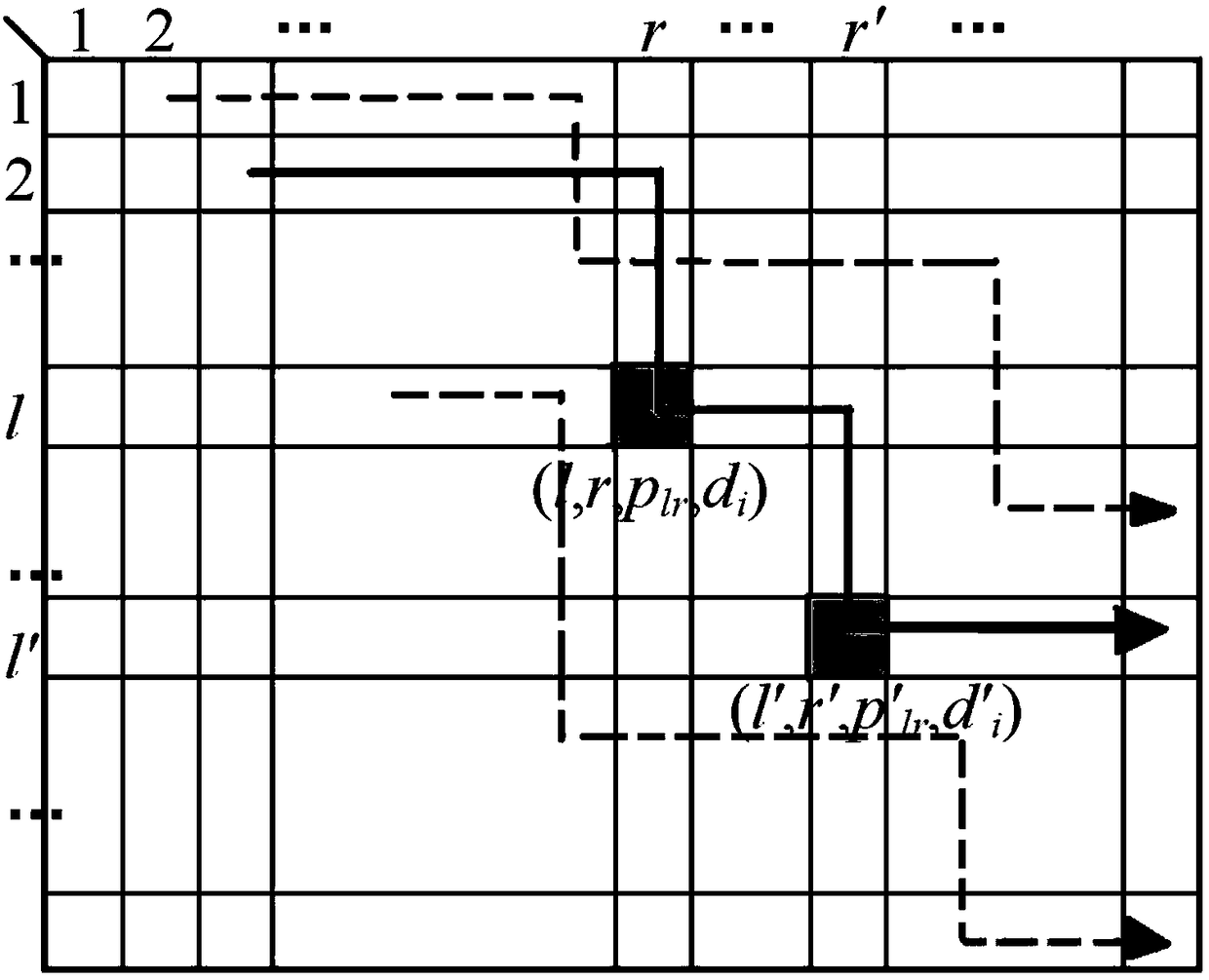
[0061] image 3 shows that in the probability matrix dynamic programming, searching for the optimal lane combination, Figure 4 A specific flow chart of searching for an optimal lane line by using dynamic programming provided by Embodiment 3 of the present invention is shown. The process is detailed as follows:
[0062] Using dynamic programming to search for the optimal lane line, the specific steps are as follows:
[0063] Step 301, find the largest k values in the probability matrix to form k combinations, the position, probability and width are (l1, r1, p1, d1), (l2, r2, p2, d2)...(lk, rk ,pk,dk);
[0064] Step 302, perform the following calculations for each type of combination from the lane line combination in the previous step: For example, the i-th combination, whose position is (li, ri), find m values rij with similar width and maximum probability in row ri, Put it into the tail of the combination to become (li, ri, rij) (1≤j≤m), and calculate the average prob...
PUM
Abstract
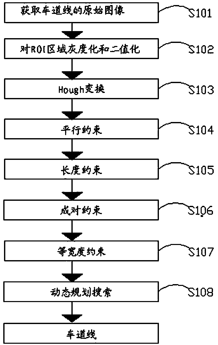
The invention provides a lane line detection method, and the method comprises the following steps: firstly setting a lower part of a lane line image and a possible lane region as an ROI; carrying outthe graying and binarization of the ROI, and then obtaining an edge image through a Canny operator; carrying out the Hough transformation of the edge image, and converting an edge line segment into aHough space from an image space; sequentially carrying out the screening and inspection of a Hough point through parallel constraint, length constraint, pairing constraint and width constraint; and searching an optimal lane combination in a probability matrix through dynamic planning. The beneficial effects of the invention are that the method irons out the defects that a conventional lane line detection method based on Hough transformation is tedious in flow and is slower in detection speed; the method achieves the direct scanning of a lane line equation through the length constraint, parallel constraint, pairing constraint and equal-width constraint in the Hough space according to a road design standard, thereby saving the process, and improving the detection speed.
Description
technical field [0001] The invention belongs to the technical field of intelligent transportation, and in particular relates to a method for detecting lane lines. Background technique [0002] In the autonomous navigation of unmanned vehicles and the intelligent assisted driving system of vehicles, it is very important to provide accurate road information. In recent decades, researchers from various countries have proposed various algorithms to realize the automatic identification of structured roads and unstructured roads, mainly using road features to fit straight line or curve models. Straight line fitting often uses Hough transform, but the discretization calculation method of this transform will make the result not correspond to the road line one by one, but decompose, fragment, repeat or even contain irrelevant line segments, so Hough The transformed detection results are transformed back into the original image space for further filtering. This processing flow makes...
Claims
Application Information
Patent Timeline
Application Date:The date an application was filed.
Publication Date:The date a patent or application was officially published.
First Publication Date:The earliest publication date of a patent with the same application number.
Issue Date:Publication date of the patent grant document.
PCT Entry Date:The Entry date of PCT National Phase.
Estimated Expiry Date:The statutory expiry date of a patent right according to the Patent Law, and it is the longest term of protection that the patent right can achieve without the termination of the patent right due to other reasons(Term extension factor has been taken into account ).
Invalid Date:Actual expiry date is based on effective date or publication date of legal transaction data of invalid patent.
Patent Type & AuthorityApplications(China)
IPC IPC(8): G06K9/00G06K9/32G06K9/46
CPCG06V20/588G06V20/62G06V10/48
Inventor罗胜方正
OwnerINST OF LASER & OPTOELECTRONICS INTELLIGENT MFG WENZHOU UNIV

