

Electronic device
A technology of electronic equipment and gap, applied in the field of electronic equipment and its control, can solve problems such as affecting user experience, reducing the effective display area of electronic equipment, etc., to achieve the effect of increasing the effective display area
- Summary
- Abstract
- Description
- Claims
- Application Information
AI Technical Summary
Problems solved by technology
Method used
Image

Examples
Embodiment 1
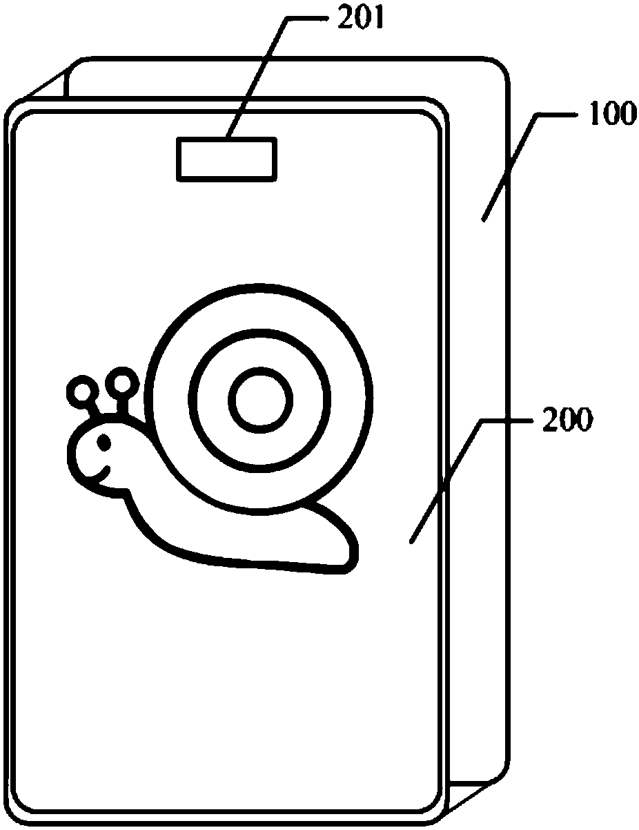
[0046] see figure 1 , figure 1 It is a structural diagram of an electronic device disclosed in this application. This electronic device includes:
[0047] Body 100;
[0048] A display screen 200, the display screen 200 is fixedly arranged on the body 100 of the electronic device, the display screen 200 has a gap 201, and the gap corresponds to the gap area;
[0049] A sensor, the sensor is used to obtain the touch input of the operating body in the notch area, so that the notch area has a touch function. exist figure 1 The specific location of the sensor is not shown in the figure.
[0050] exist figure 1 In the electronic device shown, the notch 201 is an opening on the short side of the display screen 200 , and the notch 201 is located at the upper half of the body 100 . Moreover, in figure 1 In the electronic device shown, the notch 201 is designed as a rectangle. But in actual implementation, the position and shape of the notch 201 are not limited to figure 1 sho...
Embodiment 2
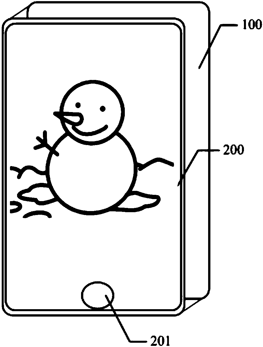
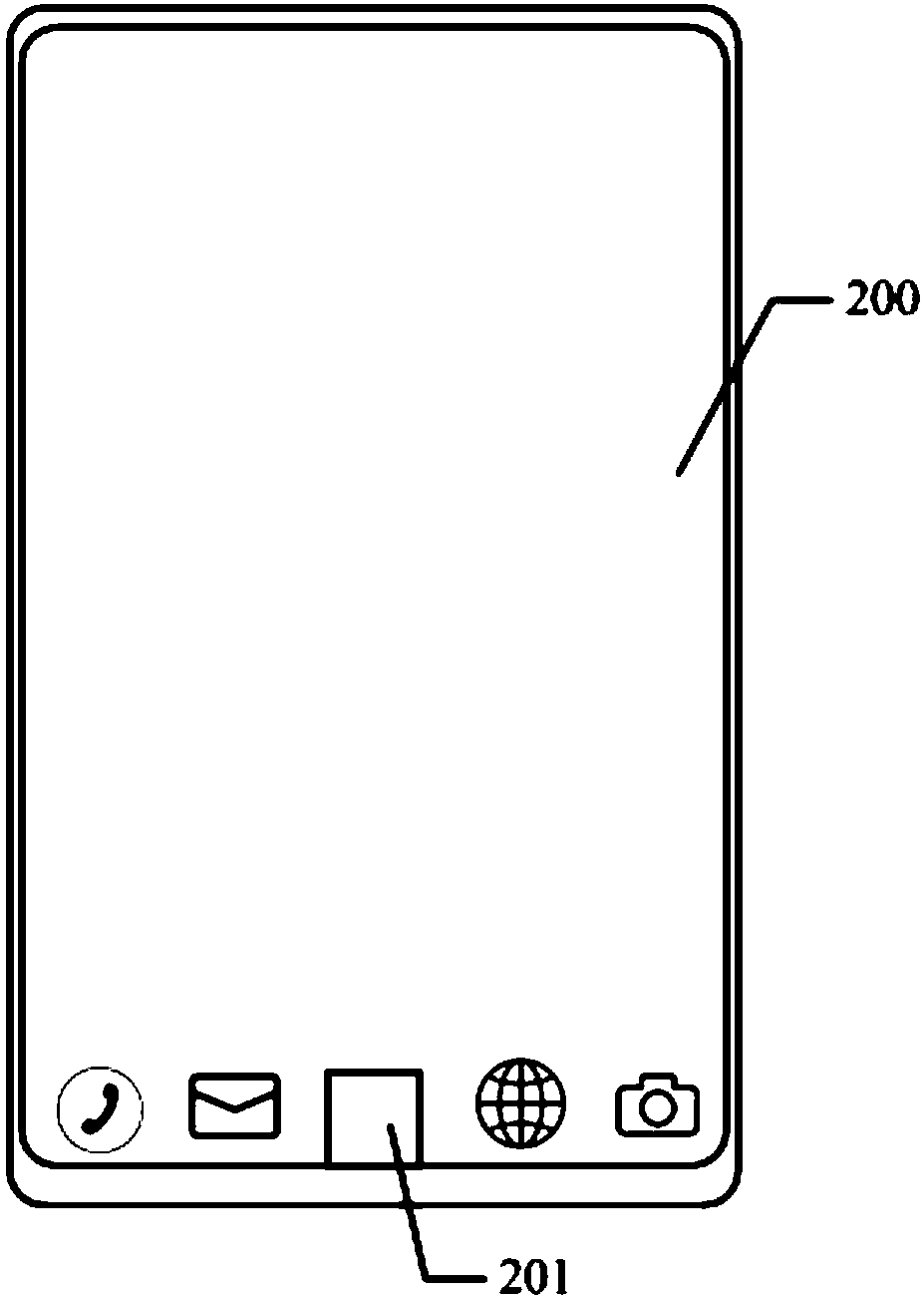
[0056] The structure of the electronic device disclosed in Embodiment 2 of the present application can be found in image 3 As shown, it includes a main body 100, a display screen 200 and sensors. Wherein, the display screen 200 is fixedly arranged on the body 100 of the electronic device, the display screen 200 has a notch 201 corresponding to the notch area, and the sensor adopts a touch sensor.
[0057] Wherein, the collection area of the touch sensor covers the display screen 200 and the notch 201, and the collection area of the touch sensor corresponds to the notch 201 is the first sensing area, and the first sensing area enables the notch area of the electronic device to have a touch function, In the collection area of the touch sensor, the second sensing area corresponds to the display screen 200, such as image 3 As shown in , the area indicated by the dotted box is the first sensing area, and other areas except this area are the second sensing area.
[0058]...
Embodiment 3
[0067] The structure of the electronic device disclosed in Embodiment 3 of the present application can be found in image 3 As shown, it includes a main body 100, a display screen 200 and sensors. Wherein, the display screen 200 is fixedly arranged on the body 100 of the electronic device, the display screen 200 has a notch 201 corresponding to the notch area, and the sensor adopts a touch sensor.
[0068] Wherein, the collection area of the touch sensor covers the display screen 200 and the notch 201, and the collection area of the touch sensor corresponds to the notch 201 is the first sensing area, and the first sensing area enables the notch area of the electronic device to have a touch function, In the collection area of the touch sensor, the second sensing area corresponds to the display screen 200, such as image 3 As shown in , the area indicated by the dotted box is the first sensing area, and other areas except this area are the second sensing area.
[0069]...
PUM
 Abstract
Description
Claims
Application Information