Light guide plate and display device using the same

a technology of light guide plate and display device, which is applied in the direction of planar/plate-like light guide, lighting and heating apparatus, instruments, etc., can solve the problems of insufficient uniformity of light flux level of plurality of light fluxes, inability to enhance light-illuminating intensity of backlight, and reduced brightness of display device, etc., to achieve low scattering of light fluxes, suppress firefly phenomenon, and widen the effect of display device effective display area

Active Publication Date: 2010-07-08
PANASONIC CORP +1
View PDF11 Cites 6 Cited by
  • Summary
  • Abstract
  • Description
  • Claims
  • Application Information

AI Technical Summary

Benefits of technology

[0013]In accordance with the light guide plate of the present invention, the light flux unifying region is separated from the light deflecting region and a region inclined to a direction of arrangement of the light sources is significantly increased in the first surface. Thereby, the light fluxes are dispersed and mixed by the reflection and refraction of the light fluxes at the inclined surface and therefore the intensity distribution of the light fluxes are adequately unified. Thereafter, the unified light fluxes are deflected, and therefore it becomes possible to adequately suppress the firefly phenomenon. Further, as a result of disappearance of the firefly phenomenon, it becomes possible to widen an effective display area of the display device using the light guide plate of the present invention. Furthermore, since the first surface is composed of a combination of the flat inclined surfaces, scattering of the light fluxes is low and the consumption of the light fluxes due to scattering loss becomes small, and therefore the display device of the present invention can achieve high brightness.

Problems solved by technology

As a result, unifying the level of a plurality of light fluxes is insufficient.
Furthermore, there was a problem that brightness of a display device is reduced since it is impossible to direct the light fluxes to an illuminating surface with efficiency.
Therefore, the light fluxes are deflected in the light deflecting region in a state of insufficient equalization.
As a result, there were problems that the light-illuminating intensity of a backlight cannot be enhanced and that an effective display area in the display device is reduced.

Method used


Image

  • Light guide plate and display device using the same
  • Light guide plate and display device using the same
  • Light guide plate and display device using the same

Examples


first embodiment

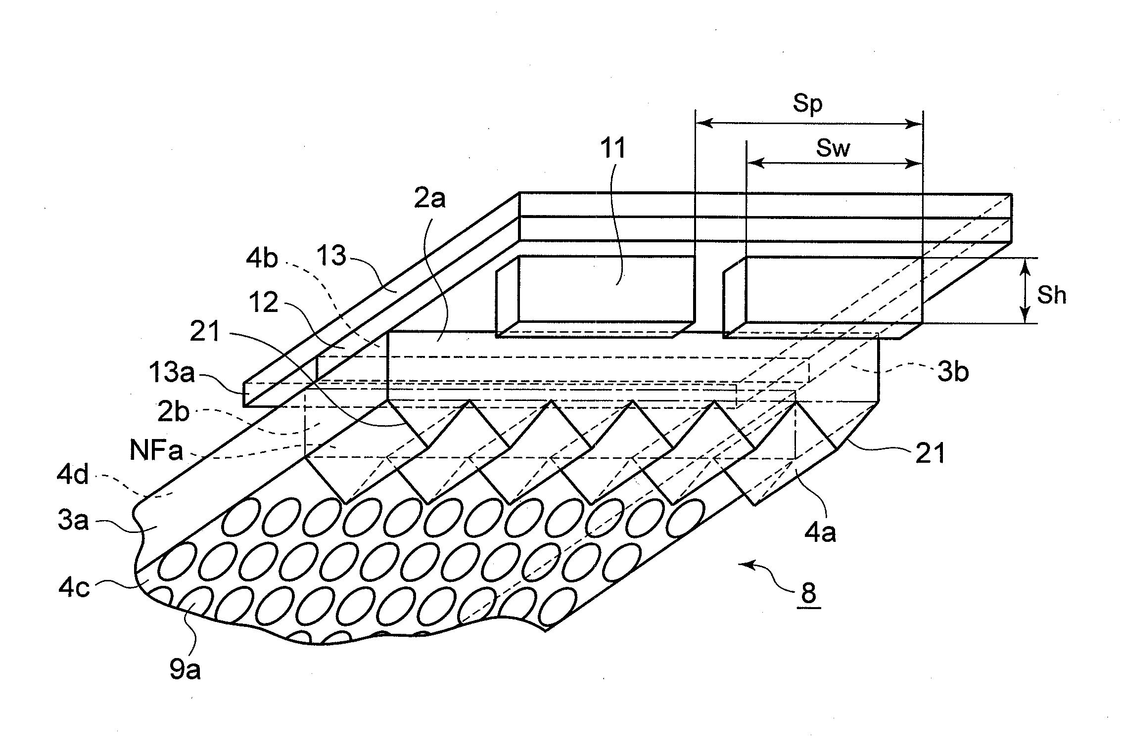
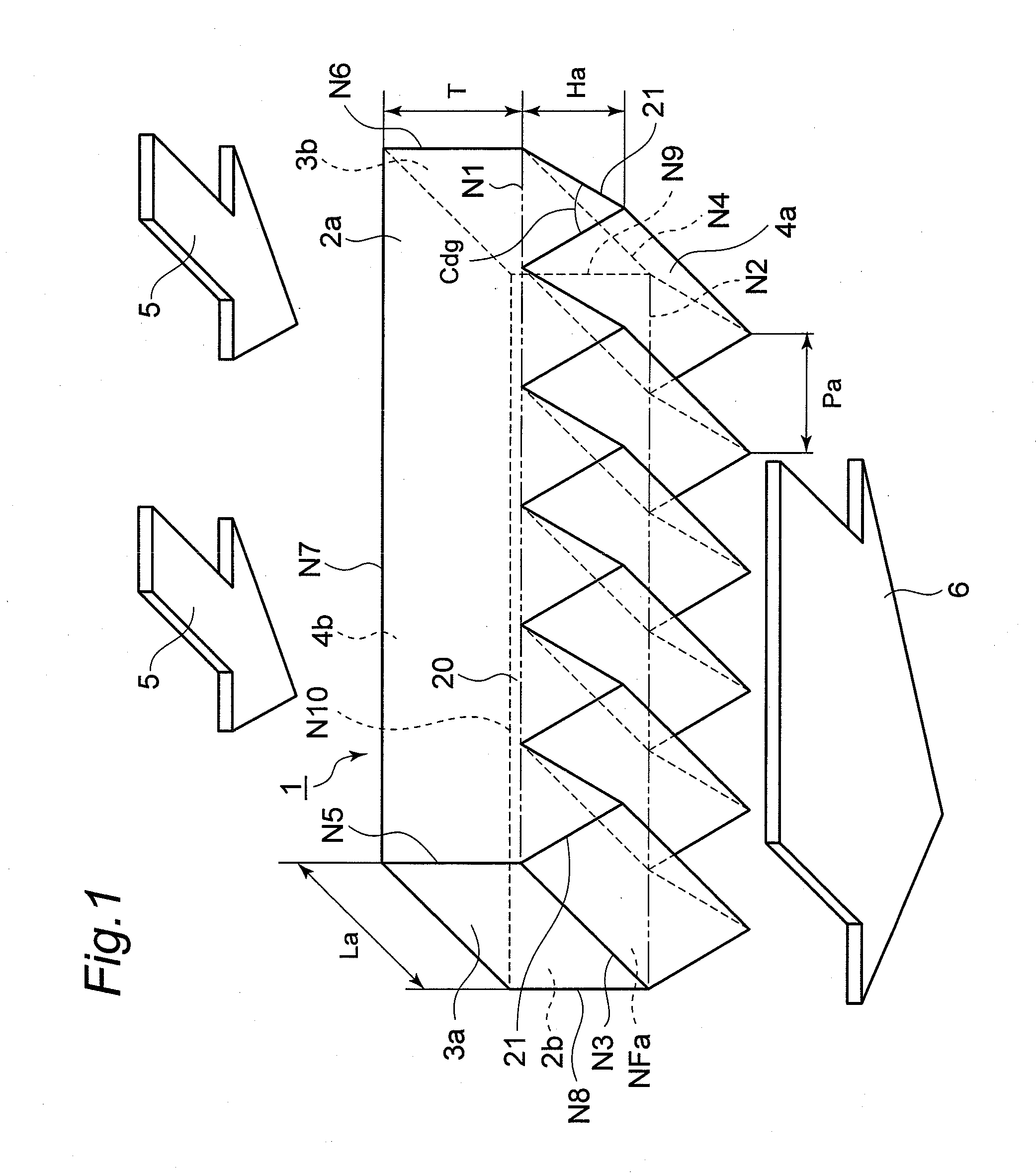
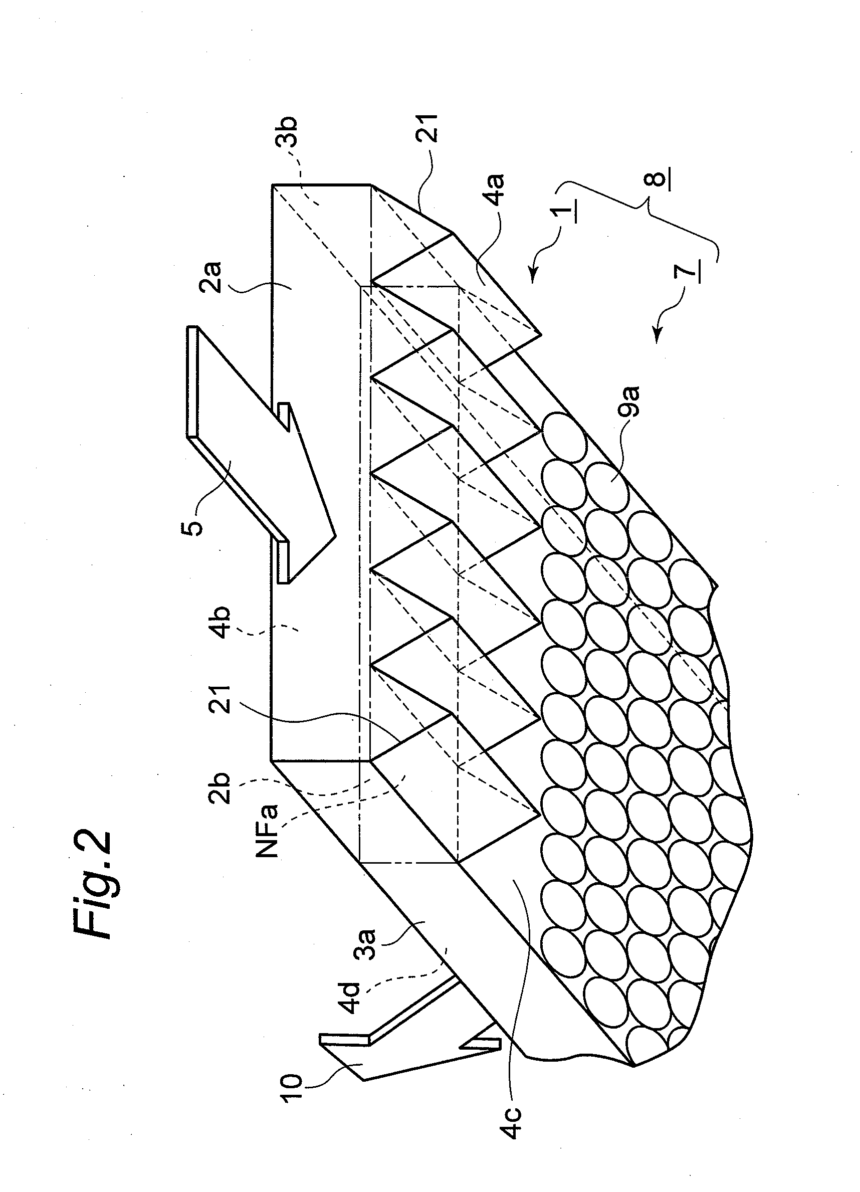
[0022]FIG. 1 is a perspective view of a light flux unifying region 1 in a light guide plate of a first embodiment. The light guide plate of the first embodiment has a tabular shape, and has an incident surface which receives incident light and a light emitting plane which unifies the incident light and emits uniform light. The light flux unifying region 1 is provided between the incident surface and the light emitting region. Only the light flux unifying region 1 is shown in FIG. 1. A plurality of parallel grooves, providing a zigzag surface, are formed on one plane of the light flux unifying region 1. This plane is preferably a plane opposite to the light emitting plane. Similar grooves may be provided on the other plane, if necessary. The grooves extend from the incident surface and the direction in which the grooves extend is along an optical axis of the incident light. Therefore, the direction of the grooves is almost perpendicular to the incident surface. The shape of the groov...

second embodiment

[0054]In the second embodiment, points differing from the first embodiment are principally described. Since other constitutions, actions and effects except these points are similar to those of the first embodiment, descriptions thereof will not be repeated.

[0055]FIG. 5 is a perspective view of a light flux unifying region 1A in a light guide plate of the second embodiment. An incident surface 2aA of the light flux unifying region 1A has inclined planes saw tooth-shaped and inclined in alternating one direction and the other direction. The incident surface 2aA is disposed in the vicinity of a virtual plane NFb. The virtual plane NFb is disposed perpendicular to the virtual plane NFa, the side 3a, side 3b and the surface 4b, respectively, across the boundary lines N1, N5, N6 and N7.

[0056]As shown in FIG. 5, a boundary line 21A between the incident surface 2aA and the virtual plane NFa forms a saw tooth shape in which a pitch Pb of the saw teeth is longer than a width Lb of the saw too...

third embodiment

[0059]In the third embodiment, points differing from the first and the second embodiments are principally described. Since other constitutions, actions and effects except these points are similar to those of the first and the second embodiments, descriptions thereof will not be repeated.

[0060]FIG. 7 is a schematic view showing a shape of a curve, having an inflection point, in a light guide plate of the third embodiment. In the light guide plate of the third embodiment, the light flux unifying surface 4a has a boundary line 21B in place of the boundary line 21. The boundary line 21B forms a shape in which a combination of two kinds of curved lines having an inflection point appears repeatedly. One kind of the curved lines has a tangent line 22a at the inflection point, and the other kind of the curved lines has a tangent line 22b at the inflection point. The tangent line 22a forms an angle Adg1 with the boundary line N1 and the tangent line 22b forms an angle Bdg1 with the boundary ...


PUM


Abstract

To solve an uneven light quantity caused in a case where a light guide plate, in which light from a spot light source such as an LED enters an surface, changes by 90 degrees and exits the light to the outside, is used as a backlight. The light guide plate of the invention includes a light flux unifying region. The light flux unifying region has an incident surface, a first surface, and an exit surface. Light fluxes emitted from a light source enter the incident surface. The first surface is almost perpendicular to the incident surface and the intensity distribution of the light fluxes having entered is unified at the first surface. The exit surface is disposed almost parallel with the incident surface and the unified light fluxes exit from the exit surface. A boundary line between the incident surface and the first surface has a zigzag surface.

Description

BACKGROUND OF THE INVENTION[0001]1. Field of the Invention[0002]The present invention relates to a light guide plate used in an illuminating device, which is used as a backlight for a liquid crystal display panel, a keyboard, or the like, and more particularly to a light guide plate and a display device using the same.[0003]2. Description of the Related Art[0004]Backlights of display devices in portable electronic equipments or the like are arranged at an end or side surface of an illuminating body from the viewpoint of reducing the thickness and weight. In this case, surface illumination becomes possible by turning an optical axis of a light flux emitted from the light source by 90 degrees using a light guide plate.[0005]Further, in recent years, a variety of light sources are used in illuminating devices from the viewpoint of energy conservation. Particularly, light emitting diodes (LEDs) receive attention as energy conserving light sources, and changeovers from cold cathode ray t...

Claims


Application Information

Patent Timeline
Patent Type & Authority Applications(United States)
IPC IPC(8): F21V7/22F21V7/04
CPCG02B6/0016G02B6/0041G02B6/0018
Inventor SAITO, TOSHIHISAFURUJIKU, MASARUISHIKAWA, TSUYOSHIHIGUCHI, EIZABURO
Owner PANASONIC CORP
Why Eureka
Try Eureka