Liquid crystal display module

A technology of liquid crystal display module and liquid crystal glass, which is applied in nonlinear optics, instruments, optics, etc., can solve the problems that transparent liquid crystal refrigerator doors cannot adapt to large-scale production, the quality impact of liquid crystal screen display, color distortion of color images, etc., and achieve Vibrant colors, maximized display area, and improved quality

Inactive Publication Date: 2016-04-06
VITROLIGHT TECH CO LTD
View PDF5 Cites 7 Cited by
  • Summary
  • Abstract
  • Description
  • Claims
  • Application Information

AI Technical Summary

Problems solved by technology

However, in the current transparent LCD freezer, the backlight used to display the image of the LCD screen is only the lighting light in the freezer. These lighting sources are installed on the top and two sides of the freezer, and cannot provide effective frontal lighting for the displayed products. , in order to increase the perspective brightness, the lighting power must be increased, but the heat emitted by the lighting strip will increase the temperature in the refrigerator, causing the refrigerator to work frequently, increasing energy consumption and shortening the service life of the equipment
At the same time, the reflected light from the various commodities placed discretely in the freezer to the transparent LCD screen is like providing a backlight with uneven brightness and dark colors and mottled colors for the transparent LCD screen, which makes the text displayed on the transparent LCD screen difficult to see clearly. The color of the image is distorted, and the quality of the LCD display is greatly affected
[0005] Due to the need to place light strips inside the refrigerator, and the need for a lot of alignment and wiring time when the transparent LCD screen is attached to the door, the current transparent LCD refrigerator doors cannot adapt to mass production.

Method used


Image

  • Liquid crystal display module
  • Liquid crystal display module

Examples


Embodiment Construction

[0032] The present invention will be described in detail below in conjunction with specific embodiments. The following examples will help those skilled in the art to further understand the present invention, but do not limit the present invention in any form. It should be noted that those skilled in the art can make several changes and improvements without departing from the concept of the present invention. These all belong to the protection scope of the present invention.

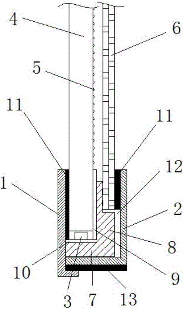
[0033] Such as figure 1 As shown, the liquid crystal display module of the present invention includes a frame of a hollow structure with an open end, and the frame is composed of a back plate 1 and a fixed outer frame 2 bonded by a sealant 13, and the back plate 1 and the fixed outer frame 2 are made of aluminum. Guaranteed strength, easy to dissipate heat.

[0034] The middle frame is installed in the chamber in the frame, specifically, the base 7 of the middle frame is arranged at the bottom of the c...


PUM


Abstract

The invention discloses a liquid crystal display module. The liquid crystal display module comprises a frame, an LED light bar, a light guide plate and liquid crystal glass, wherein the frame is of a hollow structure with an opening in one end, and a cavity is formed in the frame; the LED light bar is arranged in the cavity; the light guide plate extends into the cavity, and a light guide micro-structure is arranged on the light guide plate; the liquid crystal glass is arranged in the cavity, and the light guide micro-structure on the light guide plate faces the liquid crystal glass. Compared with the prior art, the liquid crystal display module has the advantages that the effective display area of a transparent liquid-crystal refrigerator is increased through the sealed structure, a sealing module can protrude out of existing door aluminum alloy, and maximization of the display area of a refrigerator door is achieved through gaps between sealing glass and a fixing support. The liquid crystal display module is reasonable in arrangement, simple in structure and suitable for the mass production process when the module is embedded into refrigerator glass, and production efficiency is improved.

Description

technical field [0001] The invention relates to a translucent liquid crystal display technology, in particular to a translucent liquid crystal display module. Background technique [0002] Applying transparent liquid crystal display technology to white home appliances such as refrigerators to form new home appliances and display equipment has become a hot new idea in the world in recent years. [0003] The current technology is to install a transparent LCD screen in the glass door of the refrigerator. When a white signal is input to the transparent LCD screen, the LCD screen becomes transparent. Through the refrigerator door, people can see the real goods displayed in the refrigerator. When the image signal is input, you can also appreciate the product information and advertising video dynamically displayed on the cabinet door, which has a good rendering effect of the exhibits and gives people a refreshing feeling. [0004] The LCD screen can display color images, but the L...

Claims


Application Information

Patent Timeline
Patent Type & Authority Applications(China)
IPC IPC(8): G02F1/13357G02F1/1333
CPCG02F1/133308G02F1/133603G02F1/133608G02F1/133609G02F1/133615G02F1/133317G02F1/133607G02F1/133628
Inventor 邬剑波郑国亮
Owner VITROLIGHT TECH CO LTD
Why Eureka
Try Eureka