Display apparatus for displaying multiple view angle images

a technology of display apparatus and view angle, which is applied in the direction of picture reproducers, picture reproducers using projection devices, instruments, etc., can solve the problems of improving the service life and stability of projectors, and reducing the volume and power consumption of projectors

Active Publication Date: 2016-05-03
DELTA ELECTRONICS INC
View PDF30 Cites 1 Cited by
  • Summary
  • Abstract
  • Description
  • Claims
  • Application Information

AI Technical Summary

Benefits of technology

[0011]To solve the aforesaid problems, the objective of the present invention is to provide a display apparatus for displaying images with multiple view angles, which can demonstrate a stereoscopic performance of displaying multiple view angle images by combining the advantages of the spatial multiplex method and the time multiplex method.
[0013]With the aforesaid arrangement of the present invention, the display apparatus can combine the advantages of both the spatial multiplex method and the time multiplex method to demonstrate a stereoscopic performance of displaying the images with multiple view angles and to significantly improve the visual luminance of the display panel. Furthermore, the use of the LED light sources not only significantly decreases the volume and power consumption of the projectors, but also improves the resolution, service life and stability of the projectors.
[0014]Thereby, a satisfactory stereoscopic displaying effect can be presented to the user's eyes directly. Thus, the problem with the prior art is effectively solved.

Problems solved by technology

Furthermore, the use of the LED light sources not only significantly decreases the volume and power consumption of the projectors, but also improves the resolution, service life and stability of the projectors.

Method used


Image

  • Display apparatus for displaying multiple view angle images
  • Display apparatus for displaying multiple view angle images
  • Display apparatus for displaying multiple view angle images

Examples


Embodiment Construction

[0026]In the following description, the display apparatus of the present invention will be explained with reference to embodiments thereof. However, these embodiments are not intended to limit the present invention to any specific environment, applications or particular implementations described in these embodiments. Therefore, the description of these embodiments is only for the purpose of illustration rather than limitation of the present invention.

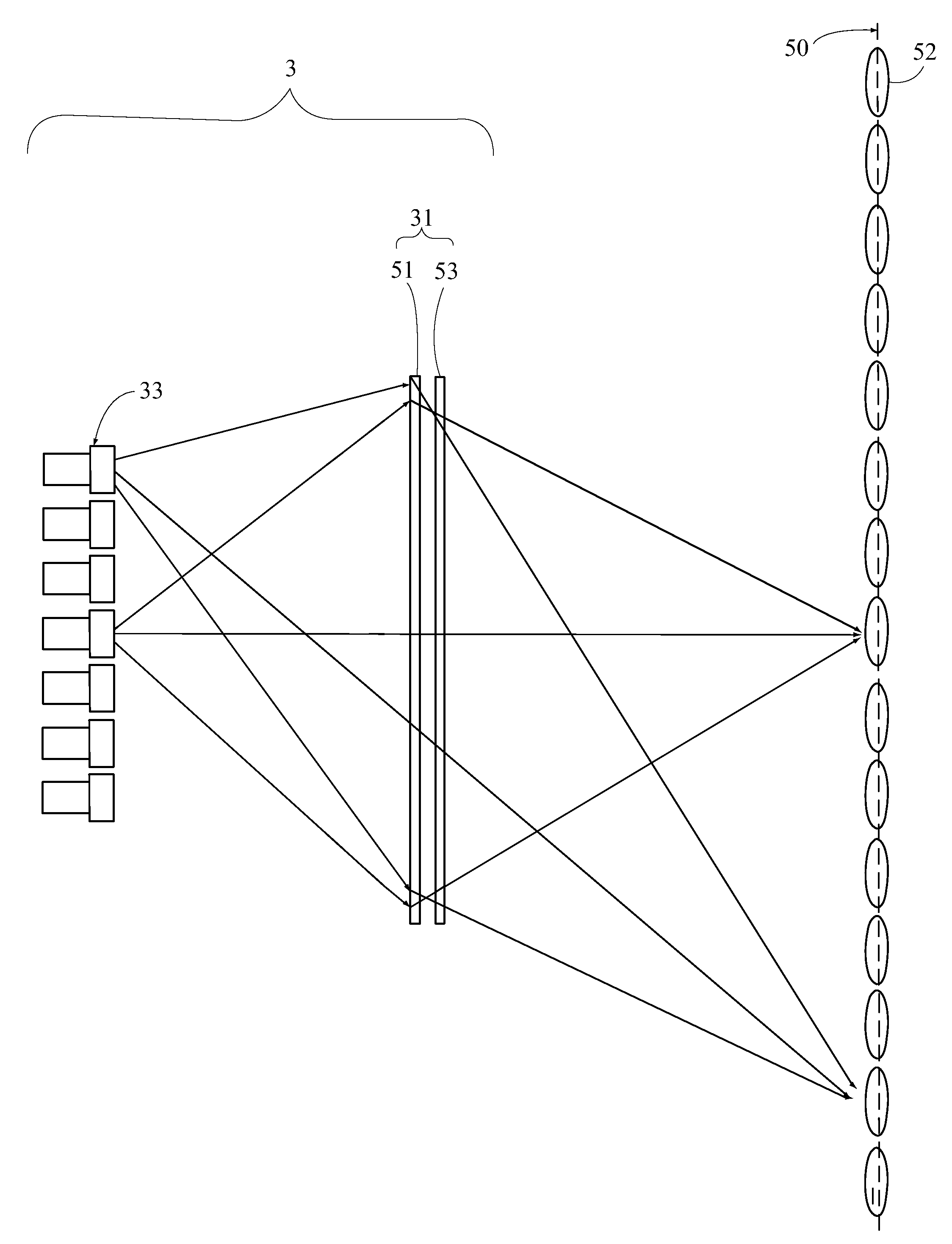
[0027]First, FIG. 3 illustrates a perspective view of the architecture of a display apparatus 3 according to the first embodiment of the present invention. The display apparatus 3 comprises a display screen 31, a plurality of projectors 33 and two flat mirrors 35 for reflecting light beams. The projectors 33 are disposed with respect to the display screen 31 and formed an array in the horizontal direction. In this embodiment, the array of the projectors 33 has two rows in the vertical direction, and the projectors 33 are arranged altern...


PUM


Abstract

The display apparatus comprises a display screen and a plurality of projectors. Each of the projectors comprises at least a light source module, a spatial light modulator and a lens. The first view angle image and second view angle image emitted from each projector are guided to a first sub-viewing zone and a second sub-viewing zone via a first light beam and second light beam, respectively. The sub-viewing zones imaged by each projector are adjacent to each other along a transverse axis sequentially.

Description

[0001]This application claims priority to Taiwan Patent Application No. 099115775 filed on May 18, 2010, the disclosures of which are incorporated by reference herein in their entirety.CROSS-REFERENCES TO RELATED APPLICATIONS[0002]Not applicable.BACKGROUND OF THE INVENTION[0003]1. Field of the Invention[0004]The present invention provides a display apparatus for displaying multiple images of multiple view angles. More particularly, the present invention provides a display apparatus with a light emitting diode (LED) based projector array, which can auto-stereoscopically display multiple view angle images by using a combination of both a spatial multiplex method and a time multiplex method.[0005]2. Descriptions of the Related Art[0006]Over recent years, stereoscopic display technology, subsequent to flat-panel display technologies, has become one of the most important technologies that are under development. Nowadays, many three-dimensional (3D) stereoscopic displays that have been di...

Claims


Application Information

Patent Timeline
Patent Type & Authority Patents(United States)
IPC IPC(8): G02B27/22H04N9/31G03B35/24H04N13/04G02B30/27H04N13/305H04N13/307
CPCG03B35/24G02B27/225G02B27/2214H04N9/3111H04N9/3147H04N13/0402H04N13/0404H04N13/045H04N13/0406H04N13/0415H04N13/0445H04N13/0447H04N13/0459H04N13/349H04N13/363H04N13/307H04N13/302H04N13/305H04N13/317H04N13/351H04N13/354G02B30/27
Inventor HUANG, JUNE-JEI
Owner DELTA ELECTRONICS INC
Why Eureka
Try Eureka