Anticorrosion protective housing for power equipment

A technology for anti-corrosion protection and power equipment, applied in transformer/inductor casings, circuits, electrical components, etc., can solve problems affecting equipment heat dissipation, waste of resources, and affect the safety of electricity use, and achieve novel design concepts, electronic Effects of migration suppression and service life extension

Inactive Publication Date: 2018-07-27
周琼
View PDF7 Cites 6 Cited by
  • Summary
  • Abstract
  • Description
  • Claims
  • Application Information

AI Technical Summary

Problems solved by technology

[0002] The transformer is a device that uses the principle of electromagnetic induction to change the AC voltage. The main components are the primary coil, the secondary coil and the iron core. When the transformer is running, it will generate heat. This heat comes from two aspects: one is the iron loss, which is the iron loss of the transformer. The heat generated by the lack of eddy current in the core; the second is the heat generated by the load current flowing through the transformer winding. It will affect the safety of electricity, therefore, there is an increasing demand for a corrosion-resistant protective casing for electrical equipment
[0003] Most of the anti-corrosion protective casings of power equipment currently on the market are airtight settings, which seriously affect the heat dissipation of the equipment, not only easily affect power consumption, but also prone to fire in serious cases; Anti-corrosion treatment of anti-rust materials not only wastes resources, but also has poor anti-corrosion effect; and some anti-corrosion shells only adopt a single anti-corrosion treatment scheme, which cannot achieve anti-corrosion effects. Corrosion protection enclosures for equipment

Method used


Image

  • Anticorrosion protective housing for power equipment
  • Anticorrosion protective housing for power equipment
  • Anticorrosion protective housing for power equipment

Examples


Embodiment Construction

[0022] The following will clearly and completely describe the technical solutions in the embodiments of the present invention with reference to the accompanying drawings in the embodiments of the present invention. Obviously, the described embodiments are only some, not all, embodiments of the present invention. Based on the embodiments of the present invention, all other embodiments obtained by persons of ordinary skill in the art without making creative efforts belong to the protection scope of the present invention.

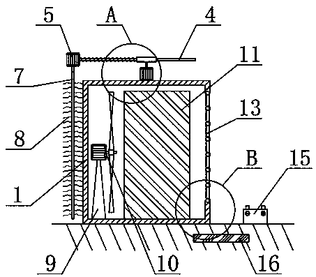
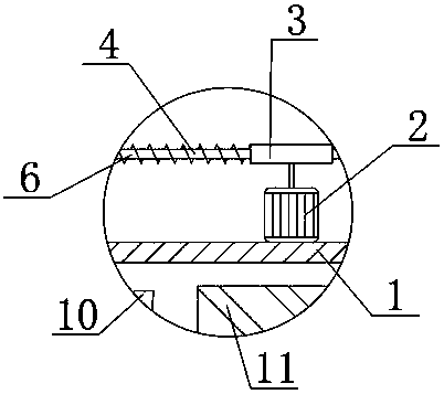
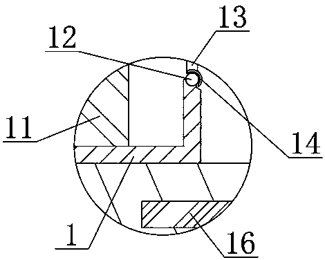
[0023] see Figure 1-5 , the present invention provides a technical solution:

[0024] An anti-corrosion protective casing for electric equipment, comprising a box body 1, a first motor 2 is fixedly connected to the central position of the top surface of the box body 1, and a horizontal motor 2 is fixedly connected to the central position of the top surface of the first motor 2. The sleeve 3 is provided, the sleeve 3 is slidably connected with a sleeve rod 4,...


PUM


Abstract

The invention relates to the technical field of power equipment, in particular to an anticorrosion protective housing for power equipment, comprising a box body; a first motor is fixedly connected tothe center of the top end of the box body, a sleeve that is horizontally arranged is fixedly connected to the center of the top end of the first motor, a socket rod is slidably connected inside the sleeve, a second motor is fixedly connected to the left end of the socket rod, the left end of the socket rod is sleeved with a tension spring, the left end of the tension spring is fixedly connected with the second motor, the tail end of a spindle of the second motor is fixedly connected with a rotary shaft vertically arranged, and a brush is fixedly connected to the outer side of the rotary shaft.The first motor, the socket rod, the second motor and the brush herein can clean the outer surface of the box body so that the box body is corroded by foreign matters at reduced speed; the anticorrosion protective housing is novel and scientific in design, has great economic benefit and a good market prospect and is worthy of popularization and use.

Description

technical field [0001] The invention relates to the technical field of electric equipment, in particular to an anti-corrosion protection casing for electric equipment. Background technique [0002] The transformer is a device that uses the principle of electromagnetic induction to change the AC voltage. The main components are the primary coil, the secondary coil and the iron core. When the transformer is running, it will generate heat. This heat comes from two aspects: one is the iron loss, which is the iron loss of the transformer. The heat generated by the lack of eddy current in the core; the second is the heat generated by the load current flowing through the transformer winding. When it will affect the safety of electricity, therefore, there is an increasing demand for an anti-corrosion protective casing for electrical equipment. [0003] Most of the anti-corrosion protective casings of power equipment currently on the market are airtight settings, which seriously aff...

Claims


Application Information

Patent Timeline
Patent Type & Authority Applications(China)
IPC IPC(8): H01F27/02H01F27/08B08B1/04
CPCH01F27/02B08B1/002B08B1/04H01F27/025H01F27/085
Inventor 周琼
Owner 周琼
Why Eureka
Try Eureka