Blasting device of smelting furnace

A blower device and smelting furnace technology, applied in the field of smelting process equipment, can solve problems such as fire and explosion, inconvenient use, and delay in production

Pending Publication Date: 2018-10-12
湖南金业环保科技有限公司
View PDF0 Cites 0 Cited by
  • Summary
  • Abstract
  • Description
  • Claims
  • Application Information

AI Technical Summary

Problems solved by technology

[0002] At present, the smelting furnaces used in the smelting process are all equipped with blast pipes, which pass through the furnace wall and communicate with the furnace for blowing. When the air supply system fails due to sudden power failure, failure, protection or misoperation When the pressure is high, accidents such as blockage of the air inlet and leakage of the melt from the air inlet often occur due to the failure of the operator to deal with it in time.
Blockage of the air inlet requires shutdown and dredging, delaying production and high maintenance costs
When the solution leaks seriously, the lea

Method used


Image

  • Blasting device of smelting furnace

Examples


Embodiment Construction

[0012] The present invention is described in detail below in conjunction with accompanying drawing and specific embodiment:

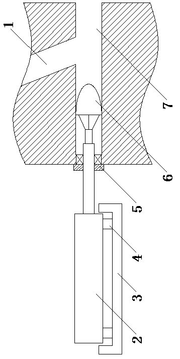
[0013] Such as figure 1 As shown, the blast device of the smelting furnace of the present invention also includes an air passage 7, an air inlet pipe 1, a plug 6, a pneumatic cylinder 2 and a pneumatic cylinder 2 controller. The gas channel 7 is placed in the furnace wall of the smelting furnace, and the outlet is connected with the hearth of the smelting furnace, and the inlet is connected with the outside of the smelting furnace. The air inlet of the air inlet pipe 1 communicates with the air source, and the air outlet is placed in the furnace wall of the smelting furnace and communicates with the air channel 7 . The plug 6 is placed in the air passage 7, behind the inlet of the air inlet pipe 1. The pneumatic cylinder 2 is fixed at the inlet of the air channel 7 and the piston rod of the pneumatic cylinder 2 extends into the air channel 7, and the ...


PUM


Abstract

The invention discloses a blasting device of a smelting furnace. The device comprises an air passage, an air inlet pipe, a plug, a pneumatic cylinder and a pneumatic cylinder controller; the air passage is formed in the furnace wall of the smelting furnace, an outlet of the air passage is communicated with a hearth of the smelting furnace, and an inlet of the air passage is communicated with the outside of the smelting furnace; an air inlet of the air inlet pipe is communicated with a wind source, and an air outlet of the air inlet pipe is arranged in the furnace wall of the smelting furnace and communicated with the air passage; the plug is arranged in the air passage and behind the air inlet of the air inlet pipe; the pneumatic cylinder is fixed at an inlet of the air passage, a piston rod of the pneumatic cylinder extends into the air passage, the piston rod of the pneumatic cylinder is fixedly connected with the plug, the piston rod of the pneumatic cylinder blocks an outlet of theair passage when stretching out, and an air outlet of the air inlet pipe is communicated with the hearth of the smelting furnace through the air passage when the piston of the pneumatic cylinder retracts; the pneumatic cylinder controller comprises an inductor and a control switch, the inductor is arranged in the air inlet pipe and electrically connected with the control switch; the control switch is electrically connected to a power source and the pneumatic cylinder respectively.

Description

technical field [0001] The invention relates to a smelting process equipment, in particular to a blast device for a smelting furnace. Background technique [0002] At present, the smelting furnaces used in the smelting process are all equipped with blast pipes, which pass through the furnace wall and communicate with the furnace for blowing. When the air supply system fails due to sudden power failure, failure, protection or misoperation When the pressure is high, accidents such as blockage of the air inlet and leakage of the melt from the air inlet often occur due to the failure of the operator to deal with it in time. Blockage of the air inlet requires shutdown and dredging, delaying production and high maintenance costs. When the solution leaks seriously, the leaked high-temperature solution will cause chain accidents such as equipment damage, fire and explosion, which is unsafe. [0003] In view of the sudden and uncertain loss of pressure in the air supply system, it ...

Claims


Application Information

Patent Timeline
IPC IPC(8): F27D7/02
CPCF27D7/02F27D2007/023
Inventor 范朝军李智李小流
Owner 湖南金业环保科技有限公司
Why Eureka
Try Eureka