Centrifugal impeller and hollow blade thereof

A hollow blade and blade body technology, applied in the field of centrifugal impeller and hollow blade, can solve the problems of deteriorating the flow condition of the suction surface, unstable fan characteristic curve, interfering with the mainstream of the suction surface, etc., achieving long calculation cycle, reducing speed, and overcoming friction. The effect of resistance

Active Publication Date: 2018-12-21
FANS TECH ELECTRIC CO LTD
View PDF6 Cites 6 Cited by
  • Summary
  • Abstract
  • Description
  • Claims
  • Application Information

AI Technical Summary

Problems solved by technology

Vortex detachment, turbulence or similar fluid movement deviates the gaseous medium from the most favorable flow direction, which reduces efficiency, impairs acoustic performance and leads to instability of the fan's characteristic curve, reducing fan efficiency
[0003] In the prior art, the designer designs the blade with a perforated structure. The airflow enters from the pressure surface and flows out from the suction surface through the airflow holes. Due to the large pressure difference between the pressure surface and the suction surface, the airflow has a high pressure when it flows out from the suction surface. The flow velocity seriously interferes with the velocity of the mainstream near the suction surface. Although it can provide kinetic energy to the low-speed fluid on the suction surface, if it is not properly controlled, it will easily deteriorate the flow conditions near the suction surface.

Method used


Image

  • Centrifugal impeller and hollow blade thereof
  • Centrifugal impeller and hollow blade thereof
  • Centrifugal impeller and hollow blade thereof

Examples


Embodiment Construction

[0022] The following will clearly and completely describe the technical solutions in the embodiments of the present invention with reference to the accompanying drawings in the embodiments of the present invention. Obviously, the described embodiments are only some, not all, embodiments of the present invention. Based on the embodiments of the present invention, all other embodiments obtained by persons of ordinary skill in the art without making creative efforts belong to the protection scope of the present invention.

[0023] In order to enable those skilled in the art to better understand the solution of the present invention, the present invention will be further described in detail below in conjunction with the accompanying drawings and specific embodiments.

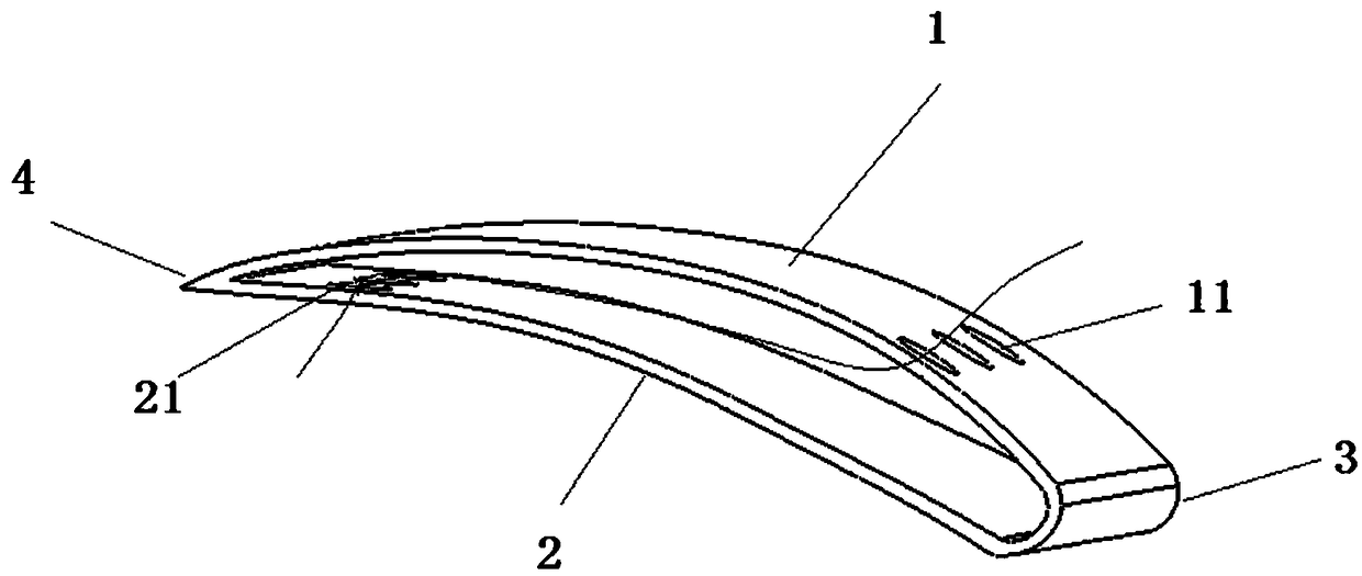
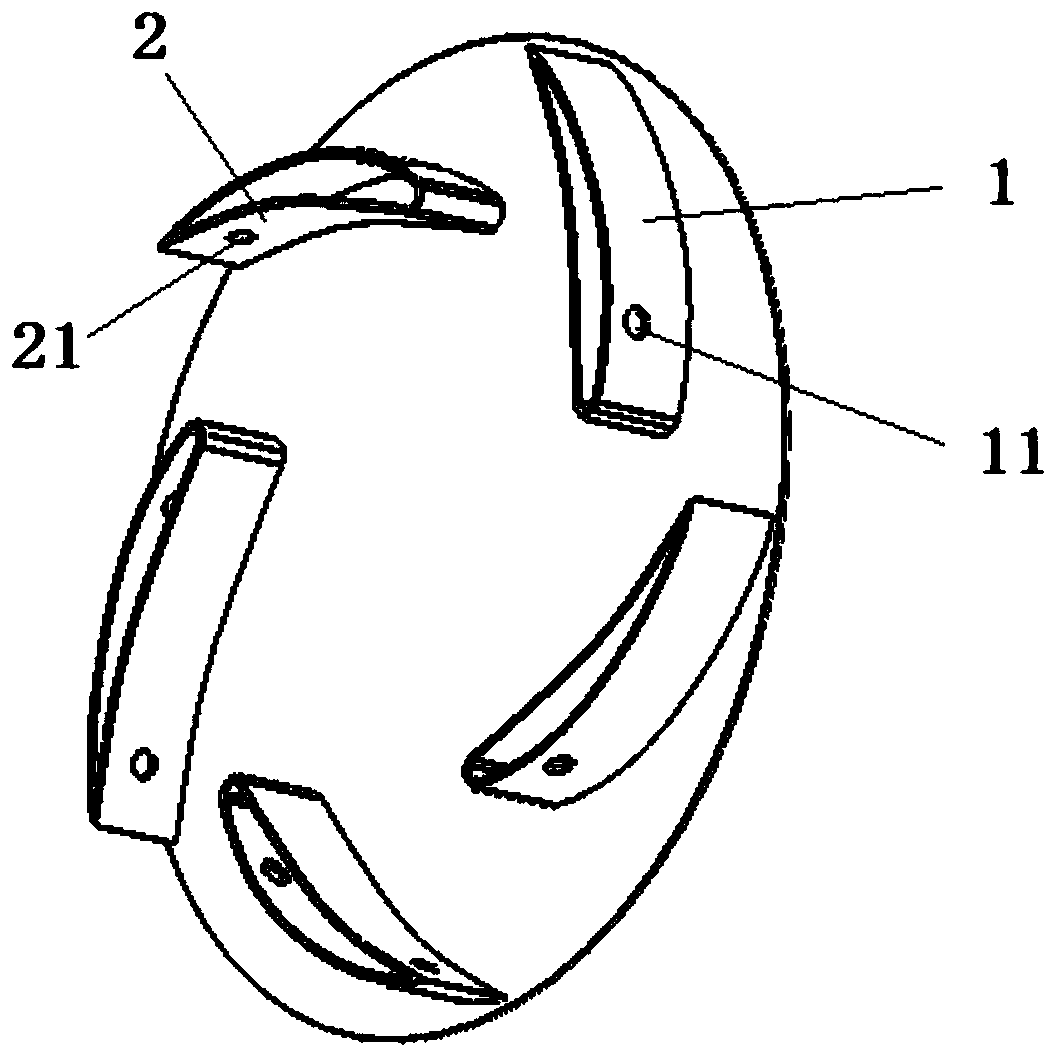
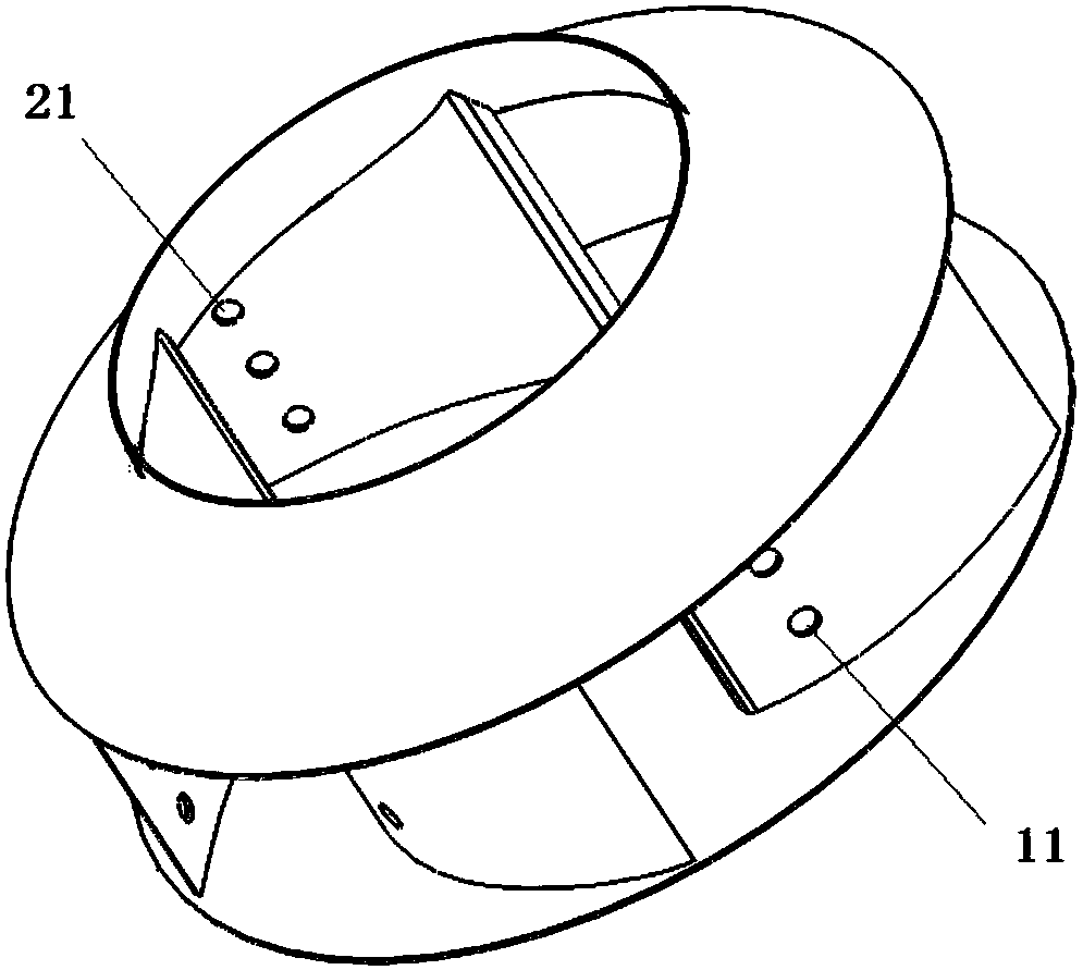
[0024] Please refer to Figure 1 to Figure 3 , figure 1 Schematic diagram of the structure of the hollow blade provided by the present invention; figure 2 A schematic diagram of the distribution of hollow blades ...


PUM


Abstract

The invention discloses a hollow blade. The hollow blade comprises a blade body provided with a cavity. A first flow passing hole and a second flow passing hole are formed in the pressure surface andthe suction surface of the blade body correspondingly, and accordingly gas on the outer side of the pressure surface can penetrate through the cavity and flow to the outer side of the suction surface.The provided hollow blade is provided with the cavity, the cavity can reduce the speed of the airflow flowing through the first flow passing hole and the second flow passing hole, the airflow flows out of the suction surface with the low and uniform speed, and influences of the airflow on main airflow in an impeller runner are reduced.

Description

technical field [0001] The invention relates to the technical field of fluid machinery, in particular to a hollow blade. The invention also relates to a centrifugal impeller comprising the above-mentioned hollow blades. Background technique [0002] The centrifugal fan performs work on the gas through the rotation of the impeller, and the power loss in the fan mainly comes from separation loss, impact loss, secondary flow loss and wake loss. The principle of separation loss is that during the flow of the gas medium in the impeller flow channel, due to the continuous increase of the cross section of the impeller flow channel, the gas flow velocity decreases slowly, which makes the thickness of the boundary layer on the blade surface increase, and for the boundary layer on the blade surface Under the action of frictional resistance, the fluid in the inner layer gradually reduces the velocity of the air flow, and the kinetic energy of the fluid outside the boundary layer decre...

Claims


Application Information

Patent Timeline
Patent Type & Authority Applications(China)
IPC IPC(8): F04D29/28F04D29/30F04D29/66
CPCF04D29/281F04D29/30F04D29/667
Inventor 陈宗华牟洁洋
Owner FANS TECH ELECTRIC CO LTD
Why Eureka
Try Eureka