Combustion system of gas-fired heating and water heating furnace

A gas heating and combustion system technology, applied to fluid heaters, lighting and heating equipment, etc., can solve the problems of rainwater and snowflakes falling into the inner cavity of the combustion device, reduce the heat of the combustion device, and fail to meet the use requirements, and achieve improved Practicality and safety, extended service life, convenient disassembly and maintenance effects

Inactive Publication Date: 2019-02-12
江苏索西热能科技有限公司
View PDF0 Cites 1 Cited by
  • Summary
  • Abstract
  • Description
  • Claims
  • Application Information

AI Technical Summary

Problems solved by technology

[0002] As the name suggests, gas heating water heaters rely on natural gas to provide hot water and heating heat. Gas heating water heaters are a new type of equipment, but gas heating water heaters need to use combustion devices during use, but now Some combustion devices have certain problems during use. For example, in the existing combustion devices, rainwater and snowflakes tend to fall into the inner cavity of the combustion device in rainy and snowy weather, which not only poses a certain safety hazard, but also reduces the heat of the combustion device. , Moreover, the existing combustion device has a complex structure, which is not convenient for regular disassembly and maintenance, which greatly shortens the service life, increases the cost and loss, and makes it unable to meet the needs of use. Therefore, we propose a gas heating heater Combustion system of water boiler

Method used


Image

  • Combustion system of gas-fired heating and water heating furnace

Examples


Embodiment Construction

[0015] The following will clearly and completely describe the technical solutions in the embodiments of the present invention with reference to the accompanying drawings in the embodiments of the present invention. Obviously, the described embodiments are only some, not all, embodiments of the present invention. Based on the embodiments of the present invention, all other embodiments obtained by persons of ordinary skill in the art without making creative efforts belong to the protection scope of the present invention.

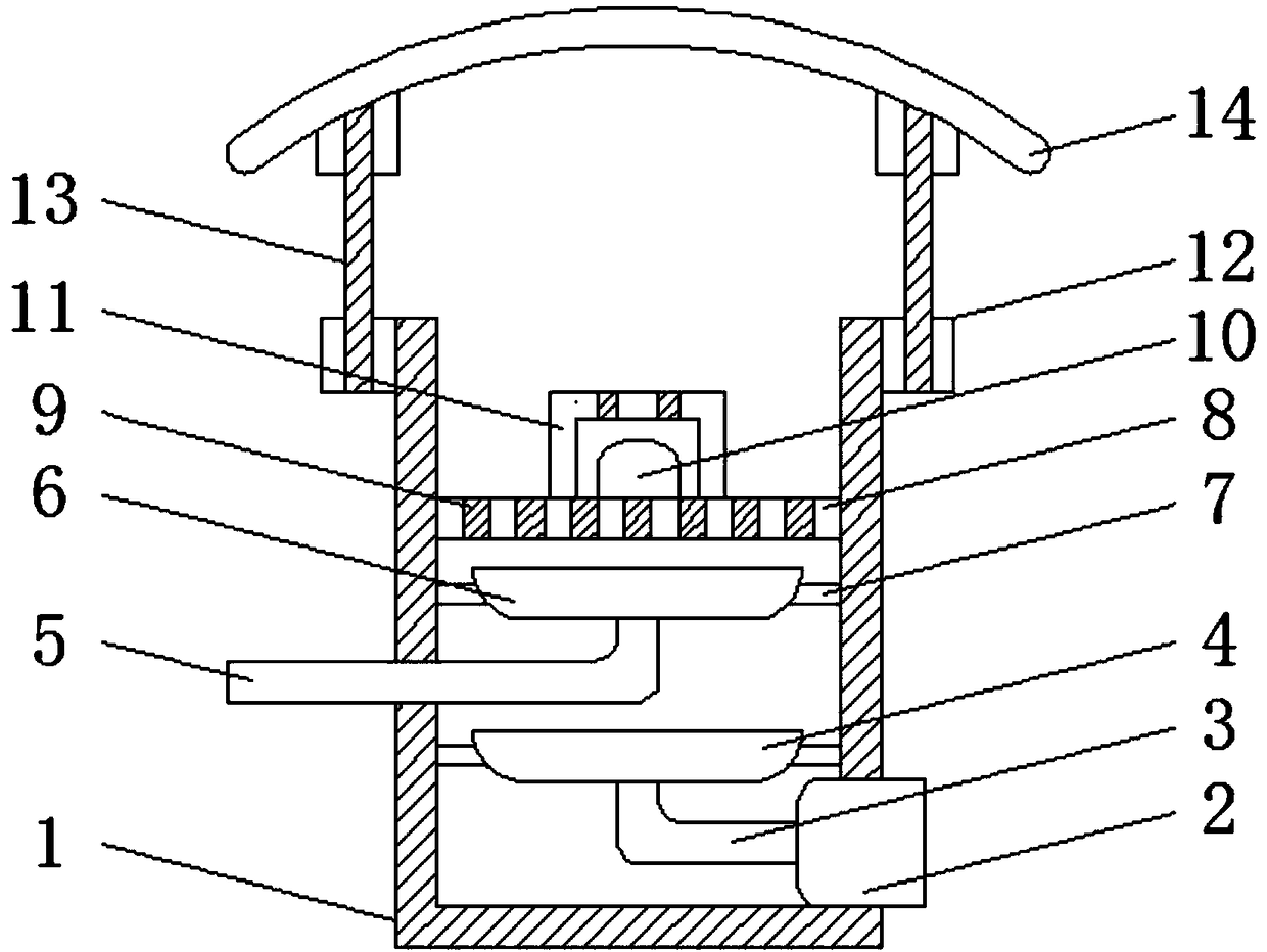
[0016] see figure 1 , the present invention provides a technical solution: a combustion system of a gas-fired heating water heater, including a combustion cylinder 1, a fan 2 is provided through the bottom of the right side of the combustion cylinder 1, and a connecting pipe 3 is provided at the output end of the left side of the fan 2 to connect The top of the left side of the pipe 3 is provided with a diverter plate 4, the middle part of the left side of the...


PUM


Abstract

The invention discloses a combustion system of a gas-fired heating and water heating furnace, and belongs to the technical field of combustion devices. A connecting pipe is arranged at the output endof the left side of a fan, a flow separation disc is arranged on the top of the left side of the connecting pipe, and an auxiliary flow separation disc is arranged on the top of the right side of a gas pipe. Exhaust holes are uniformly formed in a separating plate, and an electronic igniter is arranged in the center of the top of the separating plate. A fixing ring is arranged on the top of the outer wall of a combustion cylinder, and the tops of four arc-shaped baffles are connected through an arc-shaped baffle. Supporting rods are installed through the fixing ring on the top of the outer wall of the combustion cylinder and cooperate with the arc-shaped baffles, and therefore rainwater, snowflakes and other things in the rainy and snowy weather can be isolated, the phenomenon that due tothe fact that rainwater, snowflakes and other things fall into an inner cavity of the combustion cylinder, the temperature of the combustion cylinder is reduced is avoided, and the practicability andthe safety are greatly improved. Meanwhile, the supporting rods are conveniently disassembled by means of interference fit, the separating plate can be rapidly disassembled through elastic buckles andmatched clamping grooves and is conveniently disassembled and maintained at the regular period, and therefore the service life is greatly prolonged, and the cost loss is reduced.

Description

technical field [0001] The invention relates to the technical field of combustion devices, in particular to a combustion system of a gas heating water heater. Background technique [0002] As the name suggests, gas heating water heaters rely on natural gas to provide hot water and heating heat. Gas heating water heaters are a new type of equipment, but gas heating water heaters need to use combustion devices during use, but now Some combustion devices have certain problems during use. For example, rainwater and snowflakes tend to fall into the inner cavity of the combustion device in rainy and snowy weather, which not only poses a certain safety hazard, but also reduces the heat of the combustion device. , Moreover, the existing combustion device has a complex structure, which is not convenient for regular disassembly and maintenance, which greatly shortens the service life, increases the cost and loss, and makes it unable to meet the needs of use. Therefore, we propose a ga...

Claims


Application Information

Patent Timeline
Patent Type & Authority Applications(China)
IPC IPC(8): F24H9/18
CPCF24H9/1836
Inventor 朱永广
Owner 江苏索西热能科技有限公司
Why Eureka
Try Eureka