Strip-steel-plate continuous punching machine

A punching machine and steel plate technology, applied in the field of stamping, can solve the problems of increasing the labor intensity of the staff, increasing safety hazards, deformation of the mounting seat, etc., achieving compact and exquisite overall layout, reducing floor space, and avoiding sliding contact Effect

Active Publication Date: 2019-06-07
广东添道仓储设备有限公司
View PDF6 Cites 23 Cited by
  • Summary
  • Abstract
  • Description
  • Claims
  • Application Information

AI Technical Summary

Problems solved by technology

However, for workpieces with large plate thickness, due to the excessive pressure between the punch and the mounting seat, if the stress at the joint cannot be released evenly, it is easy to cause damage to the punch or deformation of the mounting seat
[0005] 3. In the process of punching, more waste will be produced. With the continuous production, the amount of waste is increasing. The current method is mainly to be cleaned by the staff on a regular basis, which undoubtedly increases the workload. The labor intensity of personnel also increases the probability of potential safety hazards

Method used


Image

  • Strip-steel-plate continuous punching machine
  • Strip-steel-plate continuous punching machine
  • Strip-steel-plate continuous punching machine

Examples


Embodiment Construction

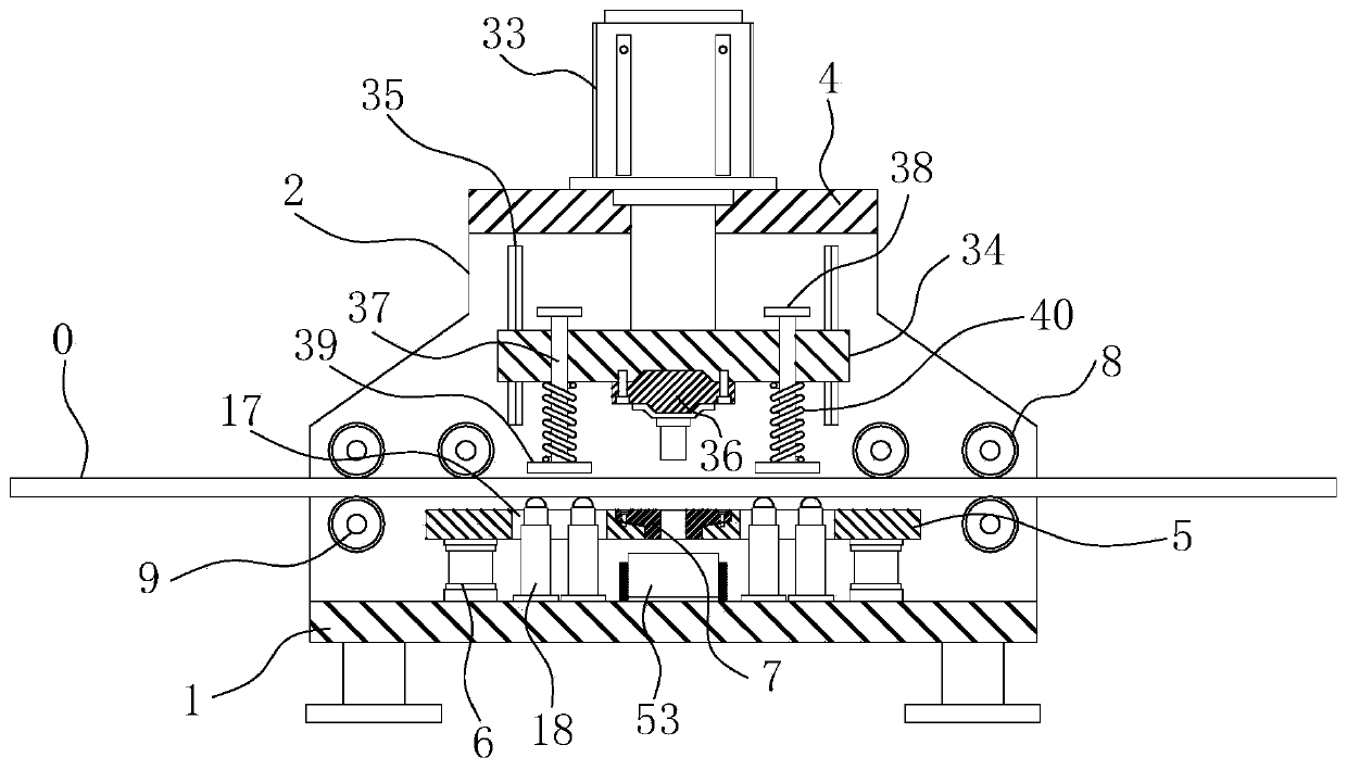
[0030] combine Figure 1-8 Shown a kind of continuous punching machine of strip steel plate, the same as traditional punching machine, the present invention mainly is made of three major parts, comprises frame, conveying device and stamping device. The frame is used to install the sub-parts of the present invention, the conveying device is used to convey the workpiece, and the stamping device cooperates with the conveying device to punch the workpiece during the conveying process. Of course, usually the present invention can also include an industrial computer for overall control of the punching frequency, conveying speed, etc. of the punching machine. Since the industrial computer of the punching machine is a relatively mature product on the market at present, the present invention no longer deals with this issue. For a detailed introduction, the designer can choose a suitable industrial computer, that is, a control system, according to actual needs.

[0031] Such as figure...


PUM


Abstract

The invention relates to the field of stamping technology and aims to provide a strip-steel-plate continuous punching machine capable of preventing workpiece abrasion. The technical scheme is that thestrip-steel-plate continuous punching machine includes a frame, a conveying device and a stamping device, wherein the conveying device comprises active conveying rollers and jacking rollers; two synchronously-rotating active conveying rollers are arranged between each left side plate and each right side plate of the front and rear ends of the frame; each active conveying roller has the same height; the bottoms of active conveying rollers are higher than the upper surface of a workbench; two jacking rollers are correspondingly arranged under the foremost and backmost active conveying rollers;and strip steel plates are located between the active conveying rollers and the jacking rollers. The conveying and stamping of workpieces are carried out at different height positions, the sliding contact between the workpieces and the workbench and concave dies is avoided, and the workpiece abrasion can be effectively prevented.

Description

technical field [0001] The invention relates to the technical field of stamping, in particular to a continuous punching machine. Background technique [0002] The punching machine is a kind of processing equipment widely used in the strip plate processing process. It can form various specifications and sizes of connection holes, installation holes, heat dissipation holes, weight reduction holes, etc. on the strip plate by punching. Make way holes, etc., greatly improve the automation level of strip plate processing and reduce the labor intensity of staff. However, there are still certain defects in its use. [0003] 1. When the existing punching machine is working, the strip workpiece gradually passes through the station directly below the punch under the action of the feeding device, and the punch is pressed down under the driving action of the hydraulic system and the pneumatic system to meet the work station. The die together punches the workpiece. However, during the ...

Claims


Application Information

Patent Timeline
Patent Type & Authority Applications(China)
IPC IPC(8): B21D28/26B21D43/09
Inventor 俞杏正
Owner 广东添道仓储设备有限公司
Why Eureka
Try Eureka