
Packer for oil field
A packer, oil field technology, used in sealing/packing, drilling equipment, wellbore/well components, etc., to achieve the effects of tight setting, increased speed and sealing effect
- Summary
- Abstract
- Description
- Claims
- Application Information
AI Technical Summary
Problems solved by technology
Method used
Image


Examples
Embodiment Construction
[0017] The following will clearly and completely describe the technical solutions in the embodiments of the present invention with reference to the drawings in the embodiments of the present invention.
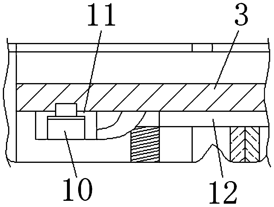
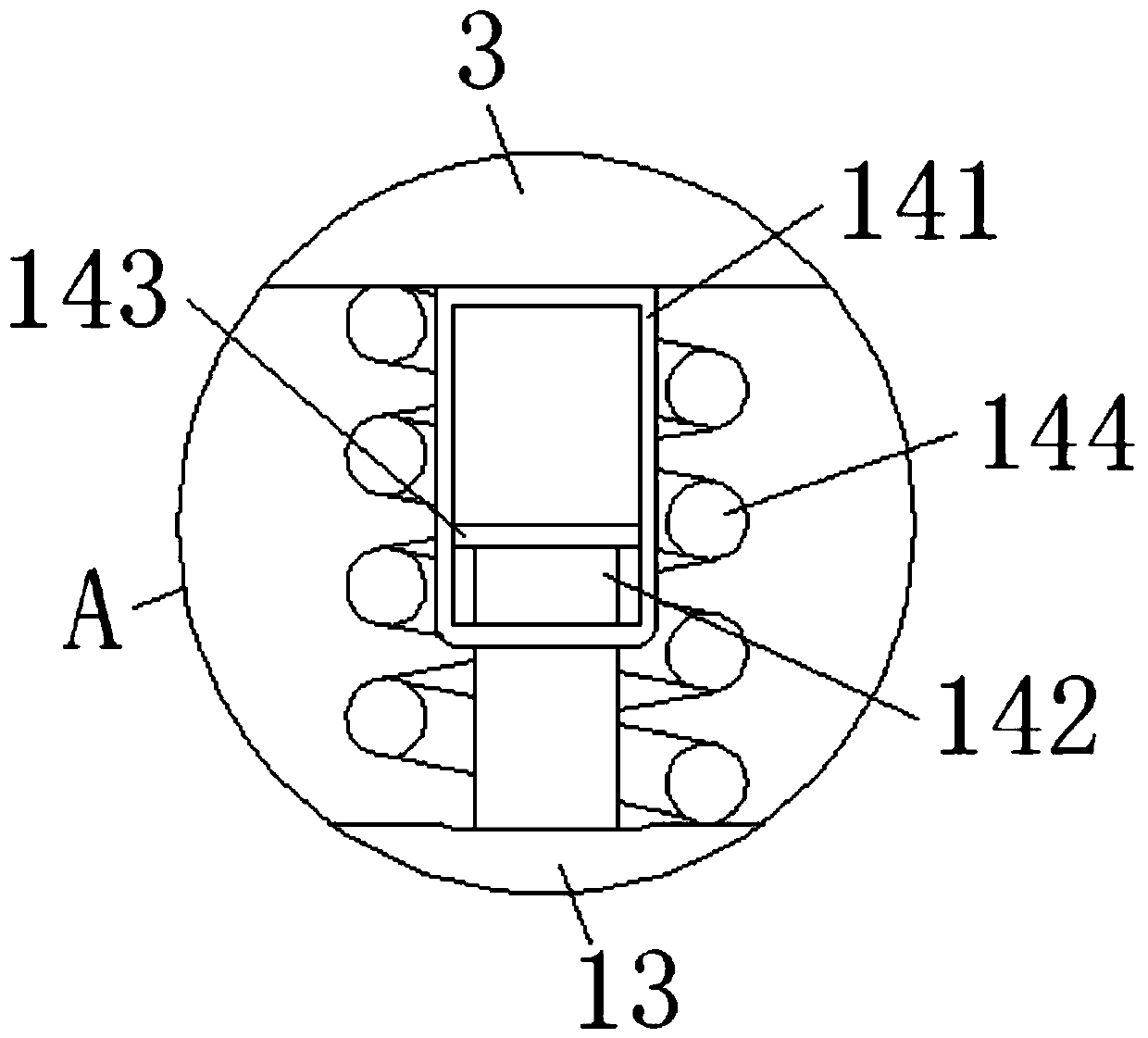
[0018] see Figure 1-4 , a packer for oil fields, comprising a right joint 1, the left side of the right joint 1 is fixedly connected with a rubber sleeve 2, the left side of the rubber sleeve 2 is fixedly connected with a centralizing sleeve 3 through a spacer ring 9, and the bottom of the inner side of the centralizing sleeve 3 An outer ring sleeve 13 is fixedly connected, and the top of the outer ring sleeve 13 is fixedly connected with the bottom of the inner wall of the centralizing sleeve 3 through a spacer structure 14. The left side of the centralizing sleeve 3 is fixedly connected with a vertebral body 17, and the compression sleeve 15 is compressed through the vertebral body 17. Carry out concentric limit, and then through the evenly distributed positioning rods 16 o...
PUM
 Abstract
Description
Claims
Application Information