Al technical title is built by PatSnap Al team. It summarizes the technical point description of the patent document.
A technology for electrical equipment and cabinets, which is applied in the field of protective cabinets for electrical equipment, can solve the problems of inconspicuous dehumidification effects and inability to effectively reduce air moisture content, and achieve obvious dehumidification effects, reduce air moisture content, and occupy a small space Effect
Inactive Publication Date: 2019-09-10
PAGMAN TECH (TAICANG) CO LTD
View PDF0 Cites 2 Cited by
Summary
Abstract
Description
Claims
Application Information
AI Technical Summary
This helps you quickly interpret patents by identifying the three key elements:
Problems solved by technology
Method used
Benefits of technology
Problems solved by technology
[0004] The purpose of the present invention is to provide a protective box for electrical equipment to solve the problem that the existing protective box for electrical equipment proposed in the above background technology mainly uses electric heating to dehumidify, and electric heating can only increase the temperature inside the box, and cannot effectively reduce the air temperature. The moisture content in the medium, the dehumidification effect is not obvious
Method used
Image
Click on the blue label to locate the original text in one second.
Reading with bidirectional positioning of images and text.
Examples
Embodiment Construction
[0020] The following will clearly and completely describe the technical solutions in the embodiments of the present invention with reference to the accompanying drawings in the embodiments of the present invention. Obviously, the described embodiments are only some, not all, embodiments of the present invention.
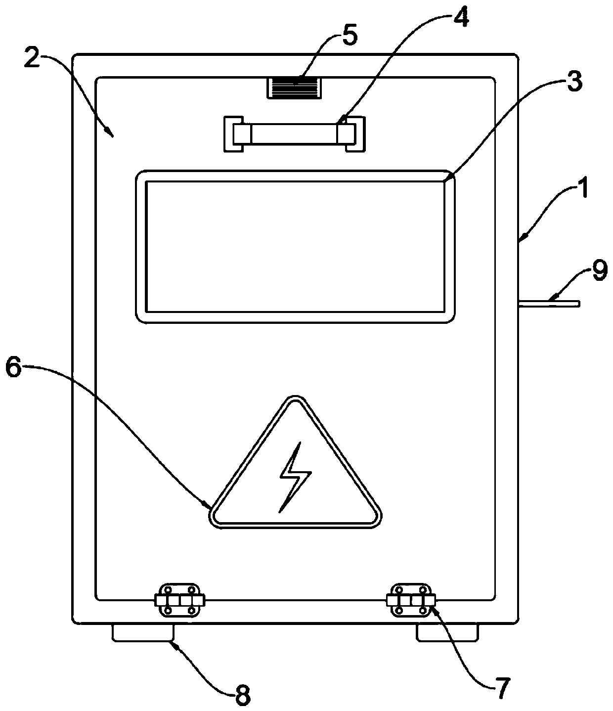
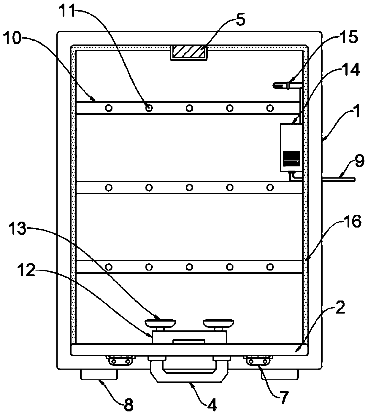
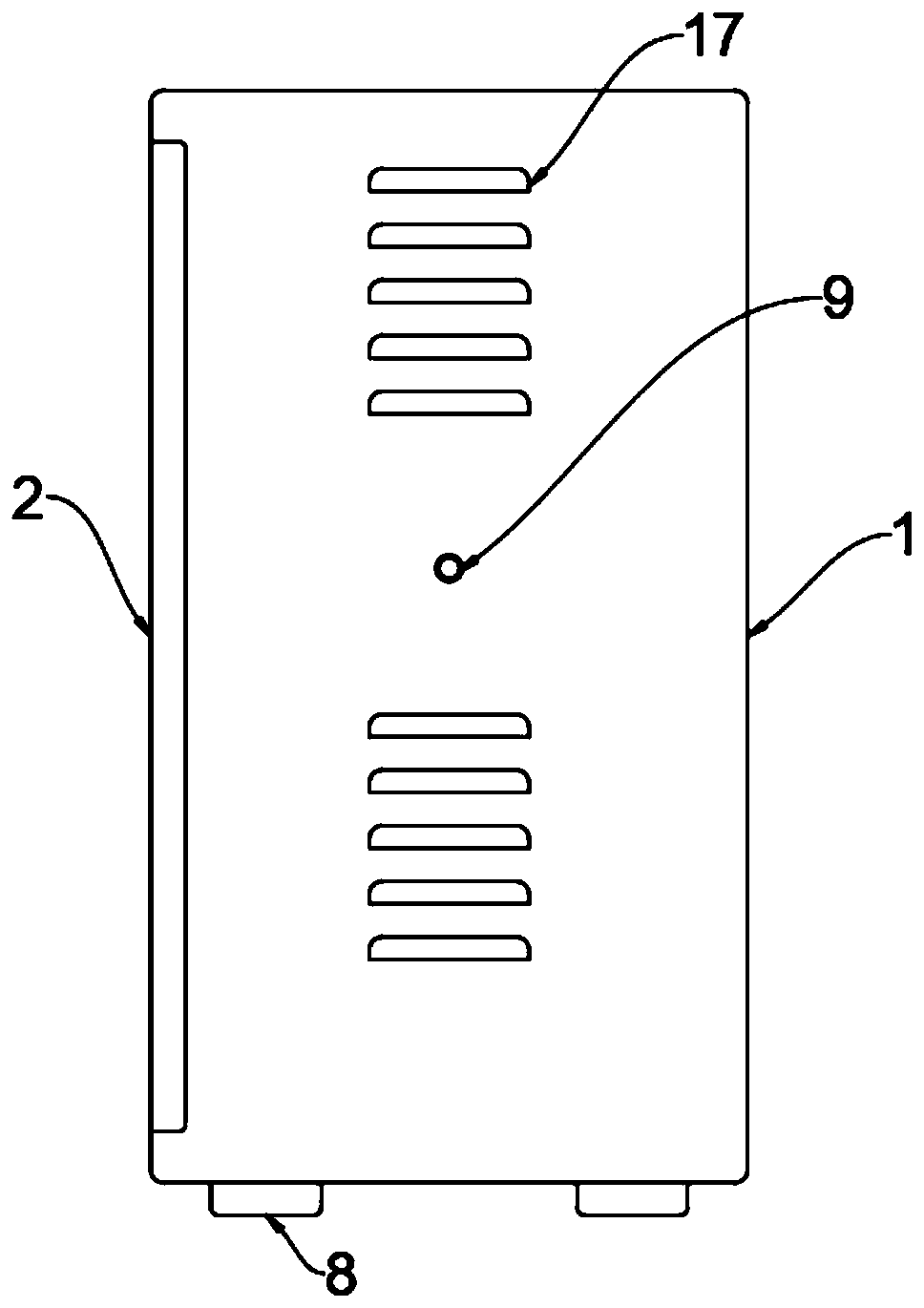
[0021] see Figure 1-4 , an embodiment provided by the present invention: a protective box for electrical equipment, including a box 1, heat dissipation louvers 17 are arranged on both sides of the box 1, and a box door 2 is installed on the front end of the box 1, An observation window 3 is installed on the front end face of the box door 2, a pull handle 4 is arranged above the observation window 3, a warning label 6 is arranged below the observation window 3, and an electrical component installation horizontal frame 10 is installed inside the box body 1, and There are three electrical parts installation horizontal frames 10, and the inside of the electrical parts i...
PUM
Abstract
The invention discloses a protection box for electrical equipment, relates to the technical field of electrical equipment, and aims to solve the problems that an existing protection box for electricalequipment mainly adopts electric heating dehumidification, the electric heating can only increase the temperature in the box, the water content in the air cannot be effectively reduced, and the dehumidifying effect is not obvious. Heat dissipation louver blades are arranged on the two sides of a box body, and a box door is arranged on the front end face of the box body; an observation window is arranged in the front end surface of the box door, and a pull handle is arranged above the observation window; a warning label is arranged below the observation window; three electrical part mounting cross frames are arranged inside the box body, and mounting through holes are formed in the electrical part mounting cross frames; an emergency lamp power supply is arranged below the interior of the box body, and two emergency lamps are arranged above the emergency lamp power supply; and a dehumidification mechanism is arranged on one side of the interior of the box body.
Description
technical field [0001] The invention relates to the technical field of electrical equipment, in particular to a protective box for electrical equipment. Background technique [0002] Electrical equipment is a general term for generators, transformers, power lines, circuit breakers and other equipment in the power system. Electrical equipment includes primary equipment and secondary equipment. Primary equipment is mainly equipment that directly generates, transmits, and consumes electric energy such as power generation, transformation, transmission, distribution, and consumption, such as generators, transformers, overhead lines, and power distribution cabinets. , Switchgear and so on. Secondary equipment is equipment that plays a role in control, protection, and metering. In buildings or general workshops such as cables, power distribution cabinets, motors, switch sockets, lamps, air conditioners, electric water heaters, electric meters, cameras, etc. are all secondary equip...
Claims
Application Information
Patent Timeline
Application Date:The date an application was filed.
Publication Date:The date a patent or application was officially published.
First Publication Date:The earliest publication date of a patent with the same application number.
Issue Date:Publication date of the patent grant document.
PCT Entry Date:The Entry date of PCT National Phase.
Estimated Expiry Date:The statutory expiry date of a patent right according to the Patent Law, and it is the longest term of protection that the patent right can achieve without the termination of the patent right due to other reasons(Term extension factor has been taken into account ).
Invalid Date:Actual expiry date is based on effective date or publication date of legal transaction data of invalid patent.