Auxiliary device for railway freight

An auxiliary device and railway freight technology, applied in the field of railway freight, can solve the problems of low work efficiency, inconvenient goods, etc., and achieve the effect of improving work efficiency

Active Publication Date: 2019-10-22
ZHENGZHOU RAILWAY VOCATIONAL & TECH COLLEGE
View PDF9 Cites 6 Cited by
  • Summary
  • Abstract
  • Description
  • Claims
  • Application Information

AI Technical Summary

Problems solved by technology

The traditional railway freight transports the goods one by one into the cargo collection box manually, the work efficiency is low, and manual handling is not convenient to ensure that the goods in each running box are equal

Method used


Image

  • Auxiliary device for railway freight
  • Auxiliary device for railway freight
  • Auxiliary device for railway freight

Examples


specific Embodiment approach 1

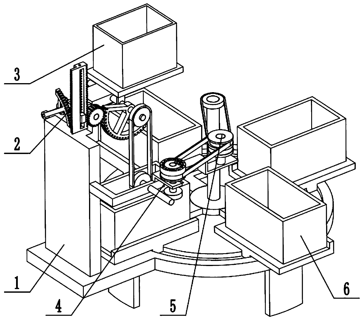
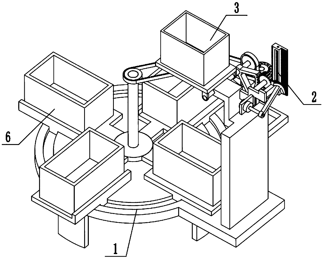
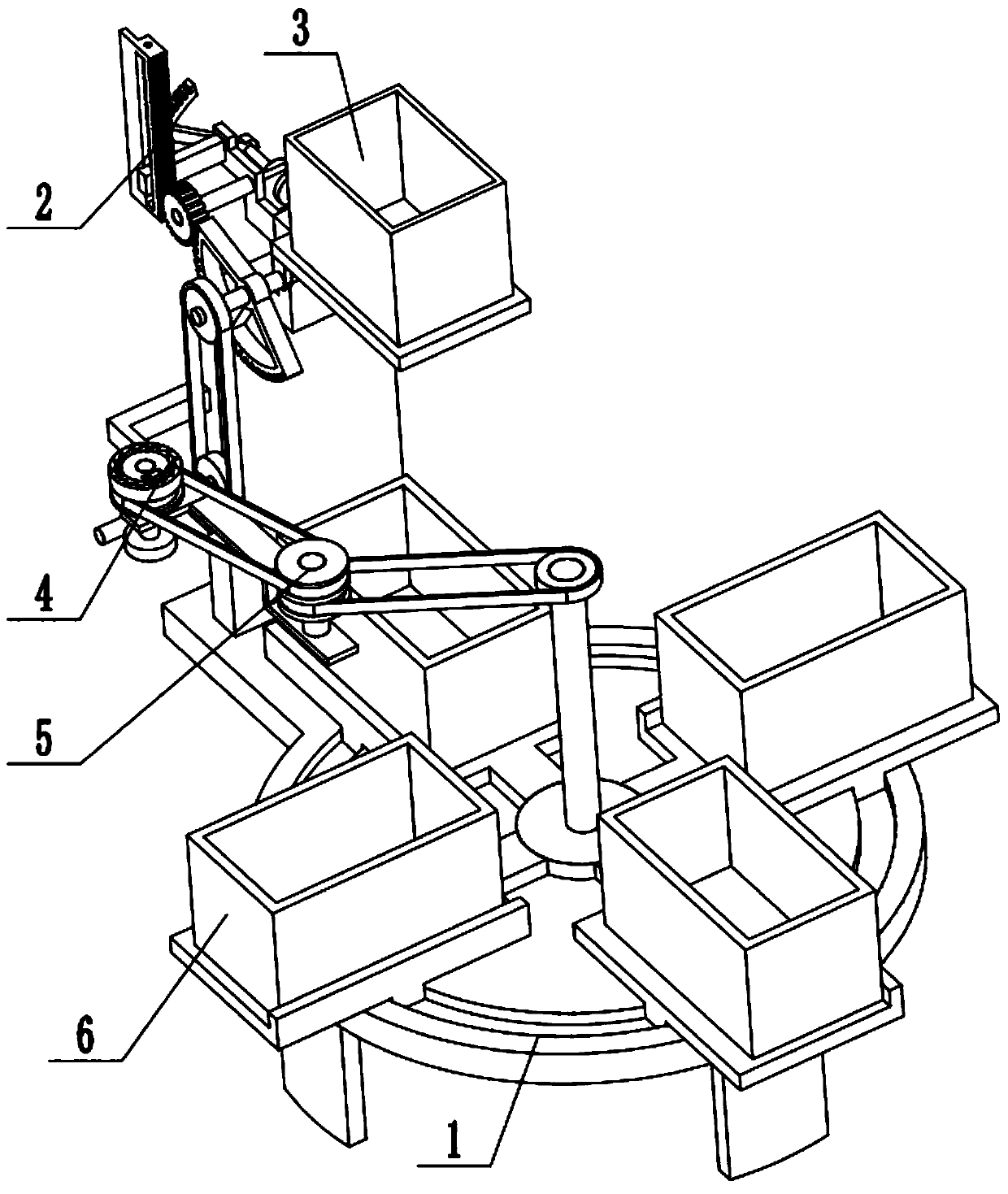
[0031] Combine below Figure 1-12 Explaining this embodiment, a railway freight auxiliary device includes a frame 1, a turning control mechanism 2, a turning box assembly 3, an intermittent rotation control mechanism 4, a power transmission mechanism 5, and a running box assembly 6. The turning control mechanism 2 Set at the upper end of the frame 1, the turning box assembly 3 is rotatably connected to the upper end of the frame 1, the turning control mechanism 2 is engaged and connected with the turning box assembly 3, and the intermittent rotation control mechanism 4 is fixedly connected to the middle of the frame 1, and rotates intermittently The control mechanism 4 and the turning box assembly 3 are connected by belt transmission, the power transmission mechanism 5 is fixedly connected to the intermittent rotation control mechanism 4, the power transmission mechanism 5 and the intermittent rotation control mechanism 4 are connected by belt transmission, and the rotation box ...

specific Embodiment approach 2

[0033] Combine below Figure 1-12 To illustrate this embodiment, the rack 1 includes a base 1-1, a supporting foot 1-2, an annular groove 1-3, a turning box swivel seat 1-4, and a supporting plate 1-5; the lower end of the base 1-1 surrounds Four supporting feet 1-2 are fixedly connected, the right end of the base 1-1 is provided with an annular groove 1-3, and the turning box rotary seat 1-4 is fixedly connected to the left end of the base 1-1 through a supporting plate 1-5.

specific Embodiment approach 3

[0035] Combine below Figure 1-12 To illustrate this embodiment, the turning control mechanism 2 includes a motor 2-1, a shaft frame plate 2-2, a rotating rod 2-3, a curved rack 2-4, a rack I 2-5, and a rack II 2-6 , Spring sleeve rod 2-7, compression spring I 2-8, limit plate 2-9, gear 2-10 and gear shaft 2-11; motor 2-1 is fixedly connected to the shaft frame plate 2-2 through the motor frame, The pedestal plate 2-2 is fixedly connected to the support plate 1-5, the output shaft of the motor 2-1 is fixedly connected to the rotating rod 2-3, and the rotating rod 2-3 is fixedly connected to the curved rack 2-4 with curved teeth The rack 2-4 is in meshing transmission connection with the rack Ⅰ 2-5, the rack Ⅰ 2-5 is fixedly connected to the rack Ⅱ 2-6, and the middle end of the rack Ⅱ 2-6 is connected to the limit plate 2-9 in a sliding fit. The inner side of strip II 2-6 is fixedly connected to the spring sleeve rod 2-7, the limit plate 2-9 is connected to the spring sleeve r...


PUM


Abstract

The invention provides an auxiliary device for railway freight, and relates to the field of railway freight. The auxiliary device comprises a rack, an overturning control mechanism, an overturning boxassembly, an intermittent rotation control mechanism, a power transmission mechanism and a transfer box assembly. The auxiliary device has the beneficial effects that cargoes are evenly distributed into each transfer box, the cargoes are equivalently distributed, it is guaranteed that the cargoes in each transfer box are equal, the operation that the cargoes are manually carried into the transferboxes one by one, and it cannot be conveniently guaranteed that the cargoes in each transfer box are equal through manual carrying is omitted, and the working efficiency is improved. The overturningcontrol mechanism is arranged at the upper end of the rack, the overturning box assembly is rotationally connected to the upper end of the rack, the overturning control mechanism and the overturning box assembly are in engaged transmission connection, the intermittent rotation control mechanism is fixedly connected to the middle of the rack, the intermittent rotation control mechanism and the overturning box assembly are in transmission connection through a belt, and the power transmission mechanism is fixedly connected to the intermittent rotation control mechanism.

Description

Technical field [0001] The invention relates to the field of railway freight transport, and more specifically to a railway freight transport auxiliary device. Background technique [0002] Railway transportation is a mode of transportation that uses railway trains to transport goods. It plays an important role in the process of social material production. Its characteristics are large transportation volume, high speed, low cost, and generally not restricted by climatic conditions. The level of technical equipment and business management has also been strengthened and improved, and they are now and in the future the main force in my country's cargo transportation. Although railway transportation has developed significantly, it still does not meet the needs of socialist construction for increased transportation tasks, and it is still a weak link in the national economy. In the adjustment of the national economy, the state has attached great importance to the development of railw...

Claims


Application Information

Patent Timeline
Patent Type & Authority Applications(China)
IPC IPC(8): B65G65/32
CPCB65G65/32
Inventor 原方方周钰爽马芳赵明丽张翠李文举
Owner ZHENGZHOU RAILWAY VOCATIONAL & TECH COLLEGE
Why Eureka
Try Eureka