Engine silencer structure with damping structures

A technology of damping structure and muffler, which is applied in the direction of engine components, machines/engines, noise reduction devices, etc., can solve the problem of unsatisfactory noise reduction effect of the muffler, and achieve the effect of improving the noise reduction effect

Inactive Publication Date: 2019-11-12
重庆合贵环保科技有限公司
View PDF6 Cites 0 Cited by
  • Summary
  • Abstract
  • Description
  • Claims
  • Application Information

AI Technical Summary

Problems solved by technology

However, the noise reduction effect of the current muffler is not ideal

Method used


Image

  • Engine silencer structure with damping structures

Examples


Embodiment 1

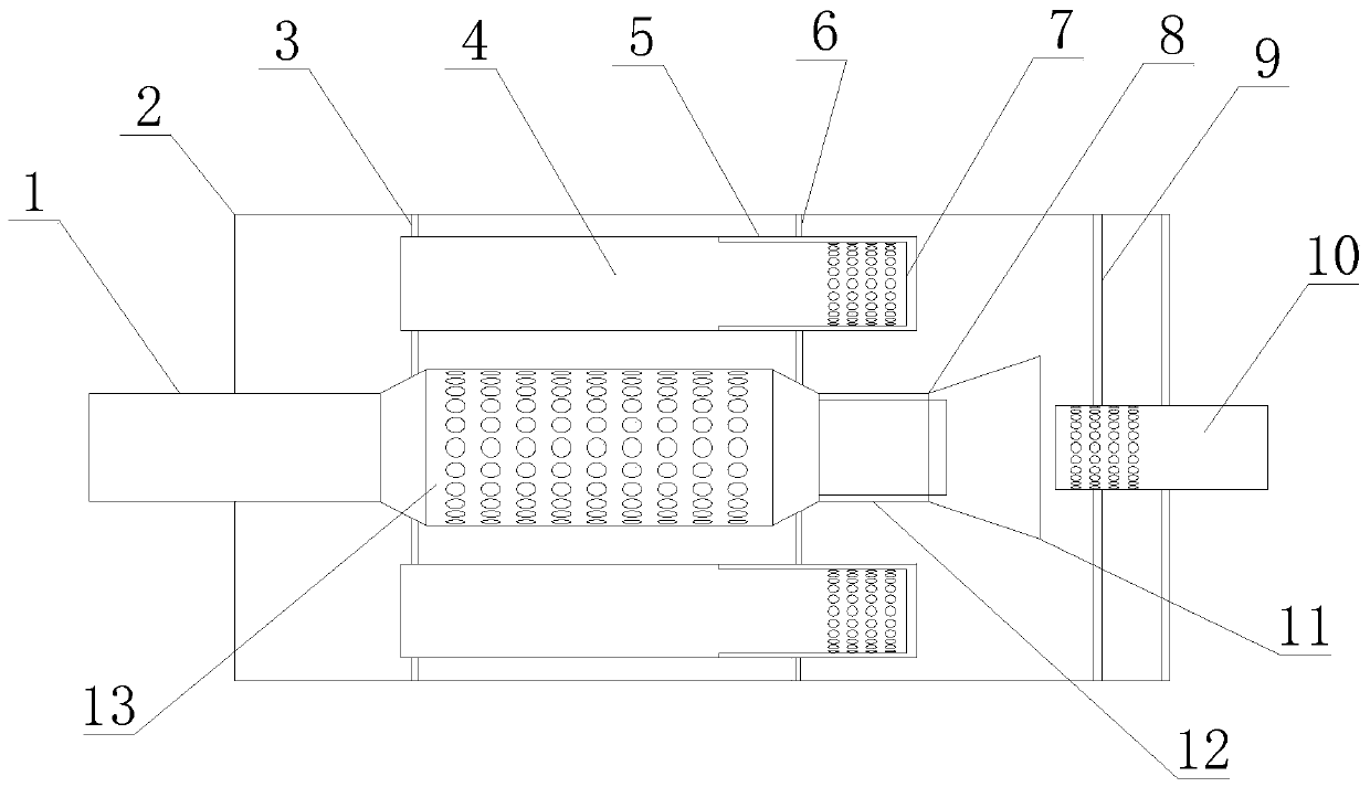
[0013] Embodiment 1 of the present invention: a muffler structure with a damping structure, including a smoke inlet pipe 1 and a sealed casing 2, one end of the smoke inlet pipe 1 is located in the casing 2, and the other end of the smoke inlet pipe 1 is located in the casing 2 outside; one end of the smoke inlet pipe 1 located in the housing 2 is connected with a first muffler pipe 13, and the first muffler pipe 13 is provided with a muffler hole; one end of the first muffler pipe 13 communicates with the smoke inlet pipe 1, and the first The other end of the muffler pipe 13 is provided with a first damping structure 8; the first damper structure 8 includes a first outer sleeve 11 and a first inner sleeve 12, and one end of the first outer sleeve 11 is fixed on the first muffler pipe 13 , the other end of the first outer sleeve 11 is sealed, the first inner sleeve 12 is sleeved in the first outer sleeve 11; the end of the first inner sleeve 12 close to the first muffler pipe 1...

Embodiment 2

[0015] Embodiment 2: A muffler structure with a damping structure, including a smoke inlet pipe 1 and a sealed casing 2, one end of the smoke inlet pipe 1 is located inside the casing 2, and the other end of the smoke inlet pipe 1 is located outside the casing 2; One end of the smoke inlet pipe 1 located in the housing 2 is connected to a first muffler pipe 13, and a muffler hole is provided on the first muffler pipe 13; one end of the first muffler pipe 13 communicates with the smoke inlet pipe 1, and the first muffler pipe 13 The other end of the first damping structure 8 is provided; the first damping structure 8 includes a first outer sleeve 11 and a first inner sleeve 12, and one end of the first outer sleeve 11 is fixed on the first muffler pipe 13, and the first The other end of the outer sleeve 11 is sealed, and the first inner sleeve 12 is sleeved in the first outer sleeve 11; the end of the first inner sleeve 12 close to the first muffler pipe 13 has an opening, and t...

Embodiment 3

[0018] Embodiment 3: A muffler structure with a damping structure, including a smoke inlet pipe 1 and a sealed casing 2, one end of the smoke inlet pipe 1 is located inside the casing 2, and the other end of the smoke inlet pipe 1 is located outside the casing 2; One end of the smoke inlet pipe 1 located in the housing 2 is connected to a first muffler pipe 13, and a muffler hole is provided on the first muffler pipe 13; one end of the first muffler pipe 13 communicates with the smoke inlet pipe 1, and the first muffler pipe 13 The other end of the first damping structure 8 is provided; the first damping structure 8 includes a first outer sleeve 11 and a first inner sleeve 12, and one end of the first outer sleeve 11 is fixed on the first muffler pipe 13, and the first The other end of the outer sleeve 11 is sealed, and the first inner sleeve 12 is sleeved in the first outer sleeve 11; the end of the first inner sleeve 12 close to the first muffler pipe 13 has an opening, and t...


PUM


Abstract

The invention discloses a silencer structure with damping structures. The silencer structure comprises a smoke inlet pipe and a sealed casing, wherein one end of the smoke inlet pipe is located in thecasing, and the other end of the smoke inlet pipe is located outside the casing; one end, located in the casing, of the smoke inlet pipe is connected and communicated with a first silencing pipe, andsilencing holes are formed in the first silencing pipe; one end of the first silencing pipe is communicated with the smoke inlet pipe, and a first damping structure is arranged at the other end of the first silencing pipe; the first damping structure comprises a first outer sleeve and a first inner sleeve, one end of the first outer sleeve is fixed on the first silencing pipe, the other end of the first outer sleeve is sealed, and the first inner sleeve is sleeved with the first outer sleeve; and an opening is formed in one end, close to the first silencing pipe, of the first inner sleeve, and the other end of the first inner sleeve is sealed. The damping structures are arranged in the silencer and the noise reducing effect of the silencer can be improved.

Description

technical field [0001] The invention relates to an engine muffler structure with a damping structure, belonging to the technical field of muffler structures. Background technique [0002] The muffler refers to the air duct with noise transmission at the same time, which can use noise reduction devices such as pipes and elbows with sound-absorbing linings or pipes with sudden changes in cross-sectional area and other pipes with discontinuous acoustic impedance to attenuate the noise in the pipe or Reflect back. It is used to reduce the exhaust noise of the engine and enable the high-temperature exhaust gas to be discharged safely and effectively. As a part of the exhaust pipe, the muffler should ensure smooth exhaust, low resistance and sufficient strength. The muffler must withstand high-temperature exhaust at 500°C to 700°C to ensure that it will not be damaged or lose its muffler effect within the specified mileage of the car. However, the noise reduction effect of the ...

Claims


Application Information

Patent Timeline
Patent Type & Authority Applications(China)
IPC IPC(8): F01N1/16F01N1/08
CPCF01N1/082F01N1/16
Inventor 金鹏冷有才吴敏周世禹肖闯方仁均
Owner 重庆合贵环保科技有限公司
Why Eureka
Try Eureka