Portable type cable twisting device

A cable reel and portable technology, which is applied in the field of portable cable reeling devices, can solve the problems of cable reeling in the same position and no adjustment device, etc., and achieve the effects of simple structure, improved efficiency and convenient use.

A cable reel and portable technology, which is applied in the field of portable cable reeling devices, can solve the problems of cable reeling in the same position and no adjustment device, etc., and achieve the effects of simple structure, improved efficiency and convenient use.

CN110790079AInactive Publication Date: 2020-02-14湖南新耒传导材料科技有限公司

Image

  • Portable type cable twisting device
  • Portable type cable twisting device
  • Portable type cable twisting device

Examples


Embodiment 1

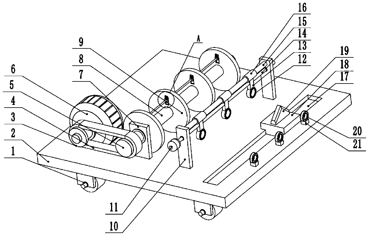
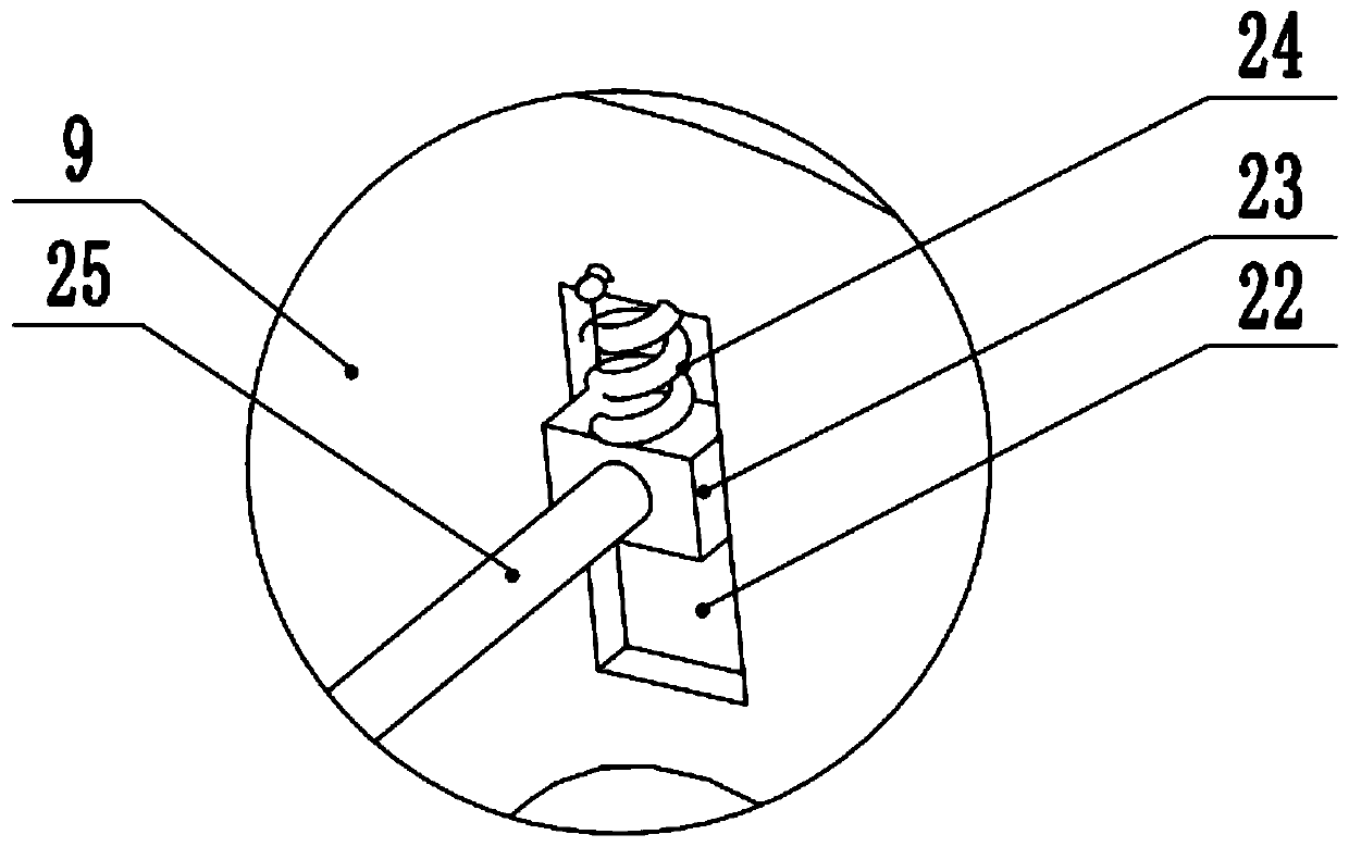
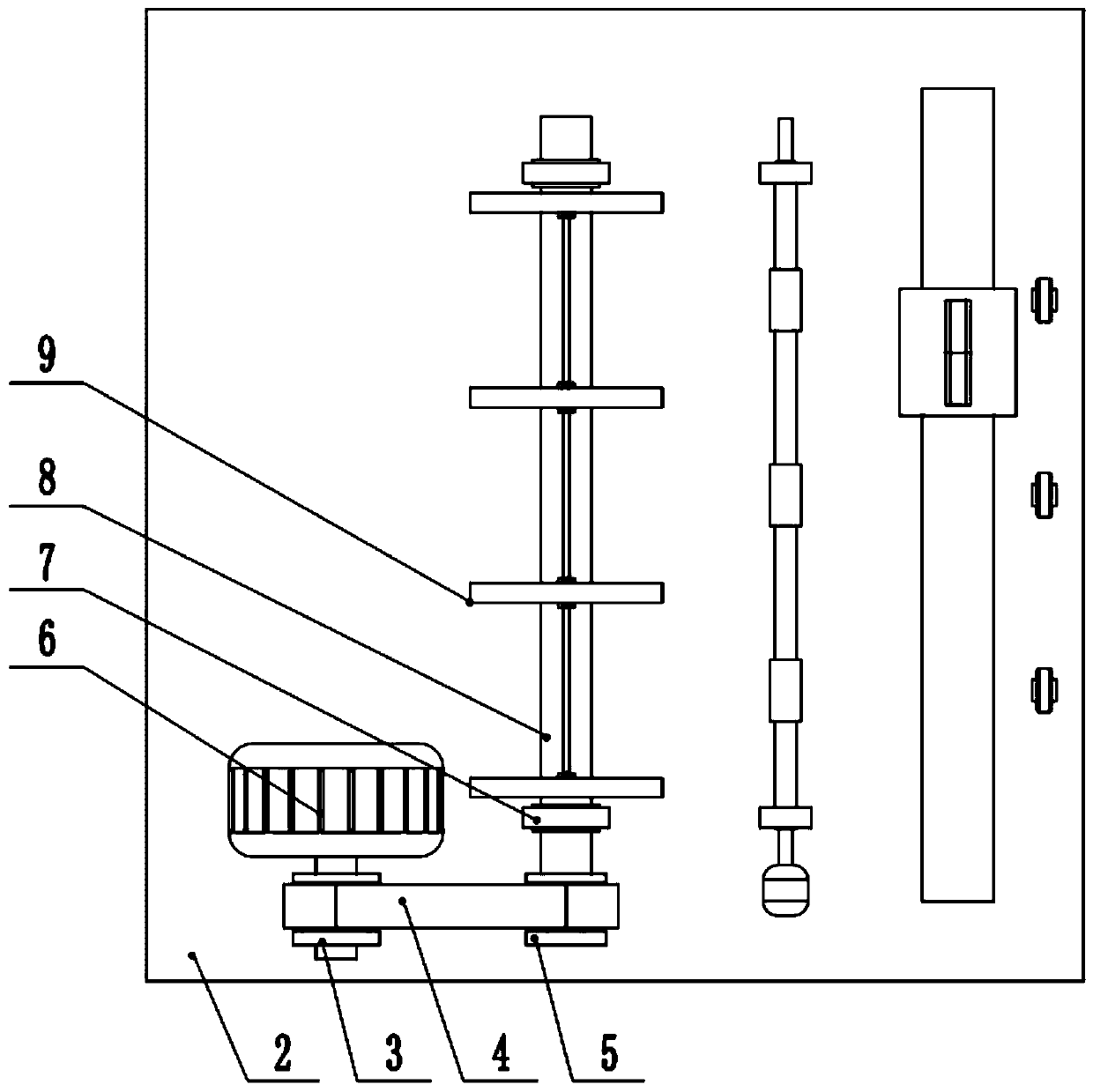
[0024] see Figure 1-3 , a portable cable twisting device, comprising a base plate 2, the left and right sides of the lower surface of the base plate 2 are provided with casters 1, the left side of the upper surface of the base plate 2 is provided with a bearing seat 7, and the upper part of the bearing seat 7 rotates the connecting disc winch roller 8, The middle part of the twisting roller 8 is provided with a baffle plate 9, and the side wall of the baffle plate 9 is provided with a second chute 22, the second chute 22 is slidingly connected to the second slide block 23, and between the second slide block 23 and the top of the chute A spring 24 is provided, and a pressure rod 25 is connected between the two second sliders 23. A drive motor 6 is provided on the left end of the upper surface of the bottom plate 2, and the output shaft of the drive motor 6 is fixedly connected to the first pulley 3. The wheel 3 is connected to the second pulley 5 through the belt 4, and the se...

Embodiment 2

[0027] see figure 1 , The other content of this embodiment is the same as that of Embodiment 1, the difference is that a base 20 is provided on the right end of the upper surface of the bottom plate 2, and a second wire hole 21 is provided on the upper part of the base 20. In order to ensure the stability when the cable is twisted, a second wire hole 21 is provided at the far right of the device, through which the position of the cable before twisting is fixed to prevent the swing of the cable from affecting the final twisting effect.

[0028] In the implementation process of the present invention, at first the free end of the cable is passed through the second wire hole 21 and the first wire hole 12, the depression bar 25 is pulled up, and the free end of the cable is placed between the depression rod 25 and the coil twist rod, Now unclamp depression bar 25, under the effect of spring 24, depression bar 25 presses the free end of cable tightly on the coiling roller 8, thereby...


PUM


Abstract

The invention relates to the technical field of cable twisting, and discloses a portable type cable twisting device. The portable type cable twisting device comprises a bottom plate, wherein the leftside of the upper surface of the bottom plate is equipped with a bearing base; the upper part of the bearing base is rotatably connected with a twisting roller; the middle part of the twisting rolleris equipped with a baffle plate; a second slide slot is formed in the side wall of the baffle plate; the second slide slot is in sliding connection to second slide blocks; a pressure rod is connectedbetween the two second slide blocks; a fixed plate is arranged at the right side of the upper surface of the bottom plate; a fixed rod is arranged at the top end of the fixed plate; the middle part ofthe fixed rod is in sliding connection with a slide sleeve; the lower part of the slide sleeve is connected with a connecting plate; a first guide wire hole is formed in the lower end of the connecting plate; the middle part of the connecting plate is fixedly connected with a slide rod; the two ends of the slide rod are in sliding connection to the middle part of the fixed plate; a first slide slot is formed in the right end of the upper surface of the bottom plate; and the middle part of the first slide slot is in sliding connection to a first slide block. According to the portable type cable twisting device disclosed by the invention, the slide rod capable of sliding front and rear is arranged to drive the first wire guide hole to move front and rear, so that a cable is uniformly twisted on the twisting roller.

Description

technical field [0001] The invention relates to the technical field of cable transportation, in particular to a portable cable twisting device. Background technique [0002] At present, the cable hinge and cable winding in most factories has been automated. The automatic equipment is evenly rewound, the pulling force of the cable is uniform, and the cable is not easy to damage. However, this tool is basically only used by large factories. [0003] In the process of selling reeled cables to users, it is true that the cable head and the cable are interlaced due to lack of special tools, making it difficult to draw the cable, and sometimes the cable insulation layer is damaged due to violent pulling , affecting construction safety. [0004] Chinese patent (notification number: CN207713154U) discloses a cable conveying device, including a bottom plate, a pull rod and a cable pulley. The other end is fixedly connected with the two ends of the pull rod respectively, one side of ...

Claims


Application Information

Patent Timeline
14 Feb 2020
Publication
CN110790079A
IPC
B65H54/28; B65H54/74
CPC
B65H54/2818; B65H54/74; B65H2701/36
Inventors
赵峥; 曾智俊