Method and lidar device for scanning scanning region with at least two pulse-encoded beams

A laser radar and scanning area technology, applied in the field of operating laser radar equipment, can solve problems such as faulty signal detection, laser radar equipment interruption, etc.

Pending Publication Date: 2020-03-06
ROBERT BOSCH GMBH
View PDF6 Cites 0 Cited by
  • Summary
  • Abstract
  • Description
  • Claims
  • Application Information

AI Technical Summary

Problems solved by technology

Another problem with LiDAR devices is the targeted irradiation of laser light - for example by laser pointers or other glare attacks (Blend attacks), which, in addition to faulty signal detection, can also induce interruptions of the LiDAR device

Method used


Image

  • Method and lidar device for scanning scanning region with at least two pulse-encoded beams
  • Method and lidar device for scanning scanning region with at least two pulse-encoded beams
  • Method and lidar device for scanning scanning region with at least two pulse-encoded beams

Examples


Embodiment Construction

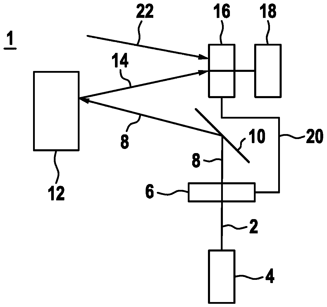
[0024] figure 1 A schematic diagram of a lidar device 1 according to a first exemplary embodiment is shown for scanning a scanning region by means of at least two beams 2 generated in temporal succession. LiDAR device 1 has a beam source 4 , for example an infrared laser 4 . A beam source 4 generates a beam 2 or laser beam 2 in the form of pulses 2 . In particular, the beam source generates at least two beams 2 following one another, which together form a pulse pattern. The pulse mode is in particular a pulse-pause mode, since each generated beam 2 or pulse 2 is followed by a pause. The generated beam 2 passes through a polarization encoder 6 after generation. The polarization encoder 6 includes in particular a linear polarization rotator and a corresponding actuation device or evaluation logic. Thus, the polarization rotator can be rotated differently, and thus an additional encoding in the form of a separate polarization for each pulse 2 can be generated for the pulse pa...


PUM


Abstract

The invention relates to a LIDAR device for scanning a scanning region with at least two temporally successively produced beams, at least one beam source for producing and for emitting the at least two beams in a pulse-pause model in the direction of the scanning region, and at least one detector for receiving at least two beams that are scattered and / or reflected on a object, the at least two produced beams being provided with different polarisations by a polarisation encoder. The detector has a polarisation analyser that compares the scattered and / or reflected beams with a defined polarisation sequence and transmits the at least two reflected beams when the polarisation sequence of the at least two scattered and / or reflected beams matches the defined polarisation sequence. The inventionfurther relates to a method for operating a LIDAR device.

Description

technical field [0001] The invention relates to a lidar device for scanning a scanning region by means of at least two radiation beams generated in temporal succession, and also to a method for operating a lidar device. Background technique [0002] For autonomous and semi-autonomous vehicles, LIDAR (Light detection and ranging) devices are necessary, for example, to determine the distance or direction of movement of objects. It is especially important here that the LiDAR device cannot be affected by the illumination of other light (eg another or identically constructed LiDAR device). It is thereby possible, for example, to detect faulty signals or ghost objects. A further problem with LIDAR devices is the targeted irradiation of laser light—for example by laser pointers or other glare attacks (blend attacks), which, in addition to faulty signal detection, can also induce interruptions of the LIDAR device. A lidar device is known from DE 10 2013 219 344 A1 in which a plura...

Claims


Application Information

Patent Timeline
Patent Type & Authority Applications(China)
IPC IPC(8): G01S17/10G01S17/42G01S17/93G01S7/481G01S7/487G01S7/495G01S7/499G01S17/931
CPCG01S17/10G01S17/42G01S7/4814G01S7/4816G01S7/4876G01S7/495G01S7/499G01S17/931G01S7/4817
Inventor A·霍莱切克T·彼得塞姆
Owner ROBERT BOSCH GMBH
Why Eureka
Try Eureka