A 3D printed micro implant guide plate and its design method

A technology of micro-implant nails and 3D printing, applied in the fields of implantology, medical science, dentistry, etc., can solve the problems of increased error, insufficient stability and accuracy, and high cost

Active Publication Date: 2021-05-18
西安交通大学口腔医院
View PDF10 Cites 2 Cited by
  • Summary
  • Abstract
  • Description
  • Claims
  • Application Information

AI Technical Summary

Problems solved by technology

However, it is still based on two-dimensional images, and there is still no accurate and reliable standard for determining the position and direction of the implantation point. Once the position judged by the doctor is inappropriate or the implantation method is not selected properly, repositioning and re-shooting are required. It may even take multiple X-rays to determine the best implant position, which is time-consuming and labor-intensive, but increases the cost of treatment
[0009] 3. At present, scholars have used CBCT to reconstruct the shape of teeth and jaws, and designed and produced micro-implant surgical guides to guide the implantation of micro-implants. However, because CBCT still cannot reconstruct the accurate shape of teeth and gums, the stability and accuracy are insufficient.
[0010] 4. At present, there is no design and production system based on three-dimensional images that is specially applied to the implantation of orthodontic micro-implants
To sum up, the three-dimensional guide plates for orthodontic micro-implant implantation published at home and abroad are divided into two categories: one uses the Simplant system, this method relies on foreign processing and design, the cost is high, the production cycle is long, and it is used for orthodontics. There is still room for improvement in the implantation of deformed and micro-implants, and no better improvement plan has been proposed yet; the other is that domestic scholars use a series of related image processing and design software to design and laser rapidly form the required guide plate. This method draws on the production process of the implant guide plate for dental implants. On the one hand, the process of image acquisition and design is complicated, and multiple 3D image processing software is required. Scanning three-dimensional images, and using external markers for overlapping registration, there is an impact of registration accuracy on the accuracy of guided implantation, which increases errors, complicates the manufacturing steps of the guide plate, and fails to solve the problem of guide plate during implantation. Sufficient Retention and Guidance Issues
[0011] 5. At present, when making a virtual micro-implant implantation plan, previous studies can only use virtual cylinders to represent the micro-implant and its implantation direction, and cannot show the actual size of the micro-implant in the bone. Positional relationship with adjacent roots
At present, the existing foreign molding software systems only include three-dimensional information of dental implants. Most of the dental implants are columnar with a large diameter, while the orthodontic micro-implants are small in diameter and mostly cone-shaped. Therefore, the existing Orthodontic micro-implants can be represented by the three-dimensional data of implants. Only through a software system that includes digital virtual micro-implant images of several orthodontic anchorage micro-implants commonly used in clinical practice, can the relationship between micro-implants and dental implants be more accurately determined. The positional relationship between the three-dimensional anatomical structures of the jaw, and formulate a more reasonable plan for simulating the direction and depth of implant placement

Method used


Image

  • A 3D printed micro implant guide plate and its design method
  • A 3D printed micro implant guide plate and its design method
  • A 3D printed micro implant guide plate and its design method

Examples


Embodiment

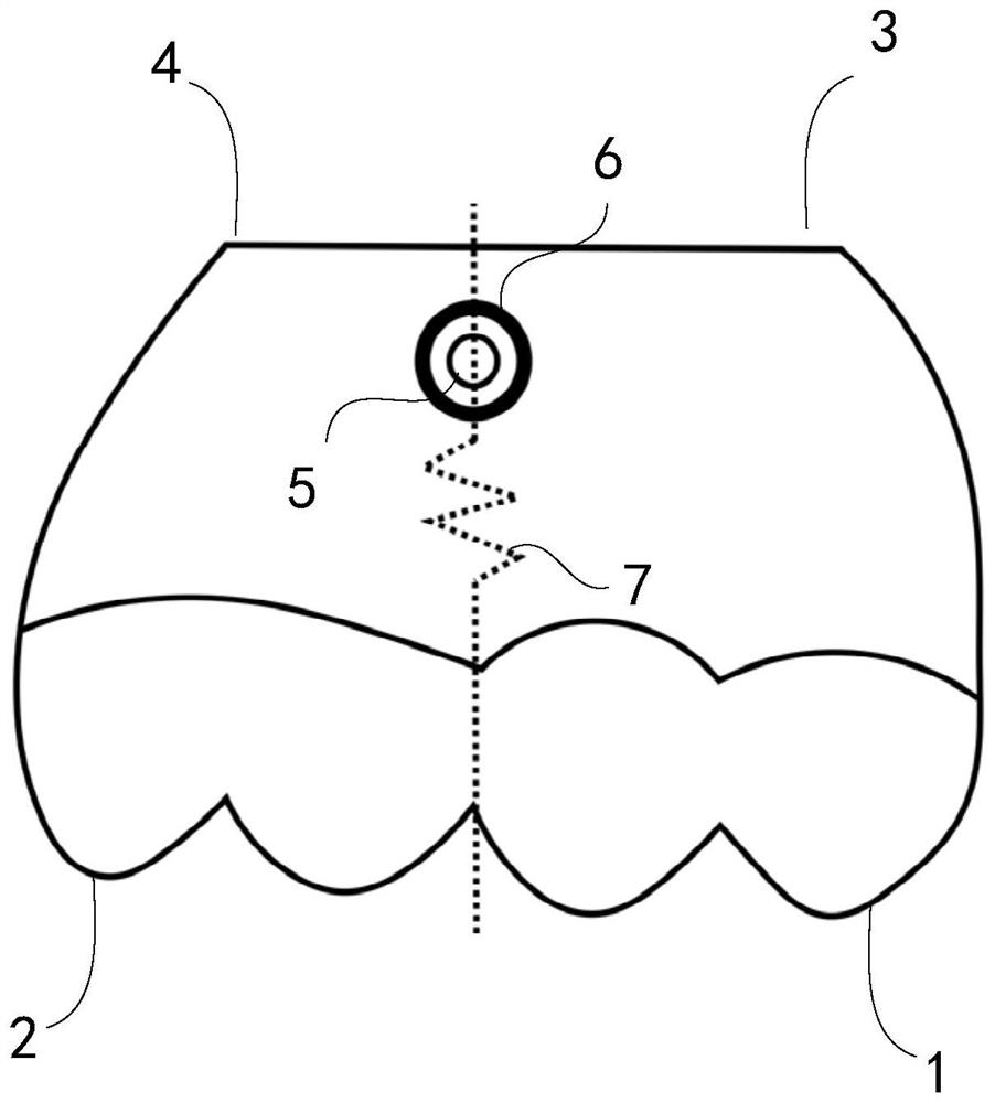
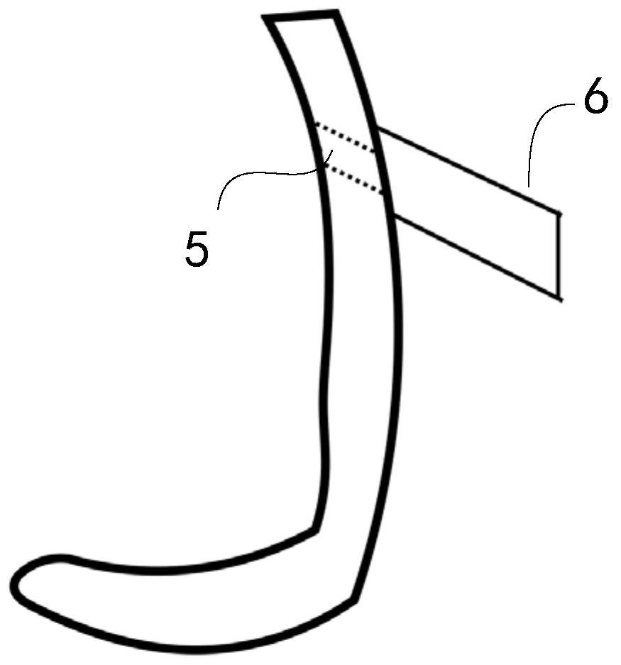
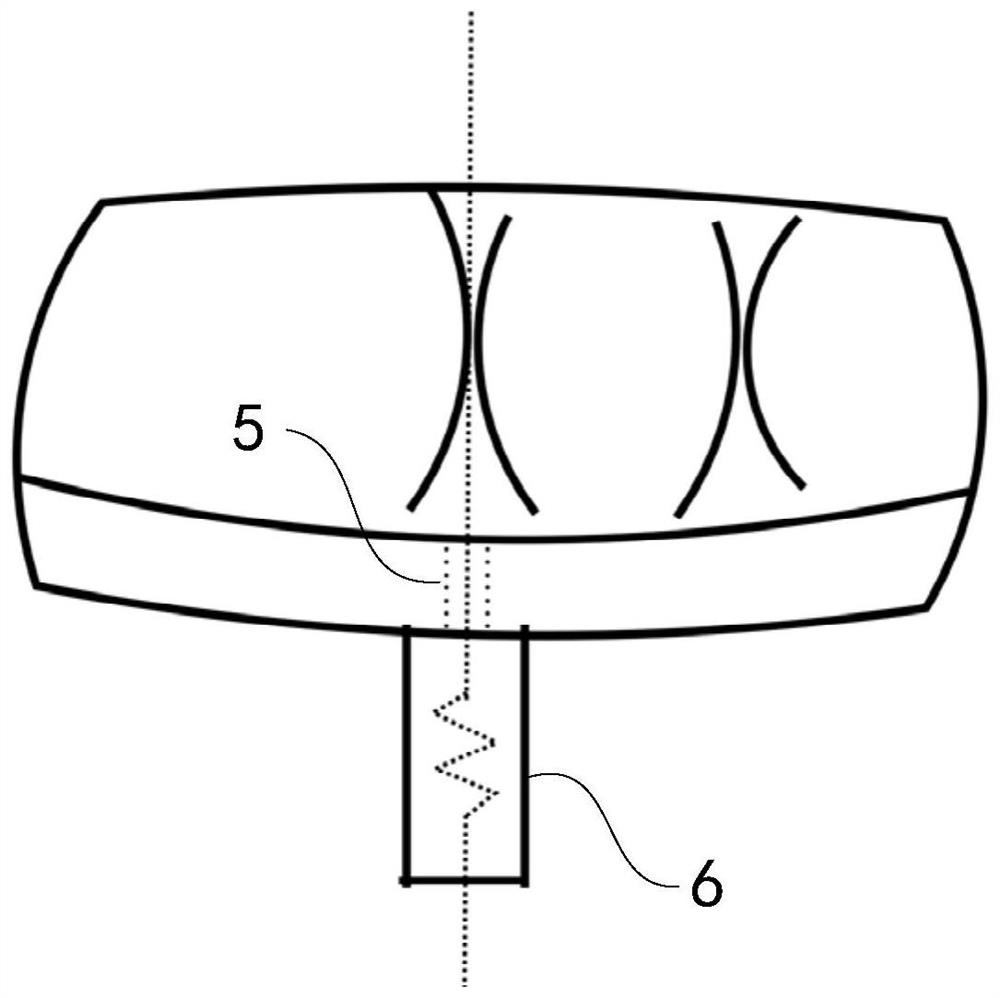
[0058] In this embodiment, it is taken as an example to plan to implant micro-screws between the maxillary first molars and the second premolars. The micro-screw guide plate includes a tooth surface retention plate, a gingiva retention plate and a micro-screw guide implantation part, with a uniform thickness of about 2-3mm. The tooth surface retention plate includes the molars and the two mesial premolars at the place where the micro-implant screws are to be implanted. When it is planned to be implanted between the maxillary first molars and the second premolars, the retention part should be the maxillary First premolars, second premolars and first molars. The gingival retaining plate includes 2-3mm from the gingival margin to the vestibular sulcus where the micro-implant is placed. The guiding part is composed of two units, one is the micro-screw insertion hole to guide the implantation site of the micro-implant, and the other is the handle guiding channel to guide the impla...


PUM


Abstract

The invention discloses a 3D printed micro-implantation nail guide plate and a design method thereof, comprising a tooth surface retention plate, a gingiva retention plate, micro-implantation nail implantation holes and a handle guide pipe. The present invention integrates CBCT jaw data, three-dimensional dentition model and micro-implantation nail data obtained by microCT scanning, which is more accurate than the method of using only jaw data or micro-implantation nail data obtained by precise scanning; the present invention At the same time, the implantation site and implantation direction of the micro-implantation nails are determined, so that the implantation of the implantation nails is consistent with the design plan, the implantation accuracy is improved, and the safety in the implantation process is ensured to the greatest extent; It is divided into two parts, which solves the problem that it is difficult to take out the guide plate after implanting the micro-implantation nails. It is ligated and fixed with the metal ligature wire commonly used in clinical practice, and it is more convenient to take out; finally, the design of the present invention is simple and easy, and can Promote and avoid the problem of touching the root of the tooth during the implantation of micro implants.

Description

【Technical field】 [0001] The invention relates to a guide plate for orthodontics, in particular to a 3D printed micro implant guide plate and a design method thereof. 【Background technique】 [0002] The anchorage of the implant is to use the biocompatibility of titanium to implant into the alveolar bone to form part or all of the bone fusion to bear the correction force and achieve the purpose of strengthening the anchorage. Because implant anchorage basically does not move in the alveolar bone and does not require a high degree of cooperation from patients, implant anchorage has been rapidly developed and spread since it was clinically used in 1999. More and more orthodontists are constantly trying to use implants as a supporting body for moving teeth, so that the treatment results do not have to completely depend on the cooperation of patients, and have achieved success in the treatment of some difficult cases where conventional methods cannot achieve satisfactory results....

Claims


Application Information

Patent Timeline
Patent Type & Authority Patents(China)
IPC IPC(8): A61C8/00A61C7/00B33Y10/00B33Y50/00B33Y80/00
CPCA61C7/002A61C8/0089A61C8/0096B33Y10/00B33Y50/00B33Y80/00
Inventor 郭昱成吉玲玲牟清楠侯玉霞管丽敏任媛
Owner 西安交通大学口腔医院
Why Eureka
Try Eureka