Power supply device

A power supply device and battery technology, applied in circuit devices, battery circuit devices, circuits, etc., can solve problems such as reduced safety and reduced electrical characteristics of battery cells

Pending Publication Date: 2020-05-12
松下新能源株式会社
View PDF6 Cites 1 Cited by
  • Summary
  • Abstract
  • Description
  • Claims
  • Application Information

AI Technical Summary

Problems solved by technology

Because the temperature rise caused by the heating of the battery cell will reduce

Method used


Image

  • Power supply device
  • Power supply device
  • Power supply device

Examples


Embodiment approach 1

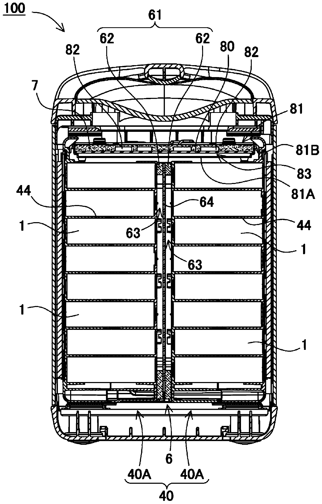
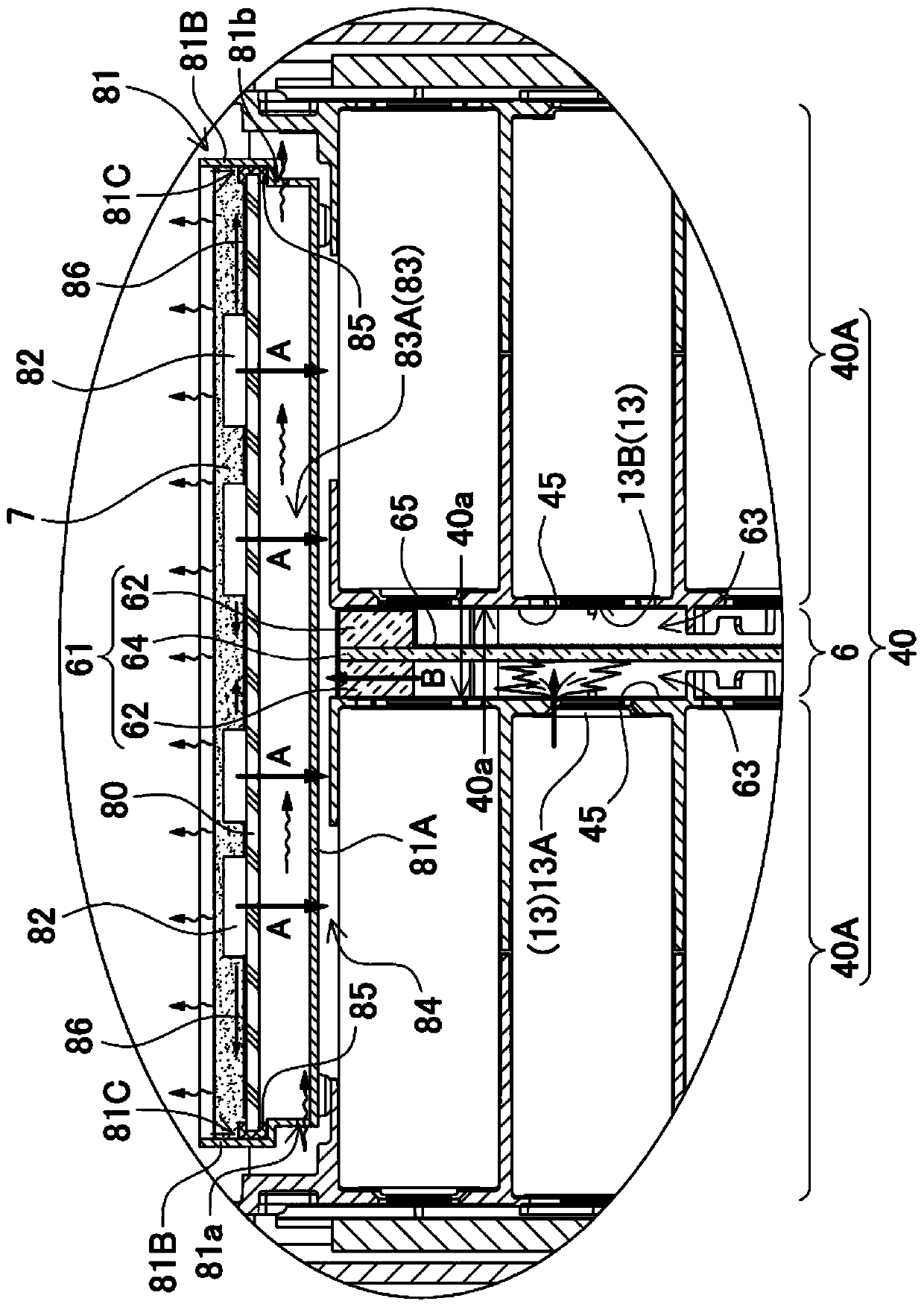
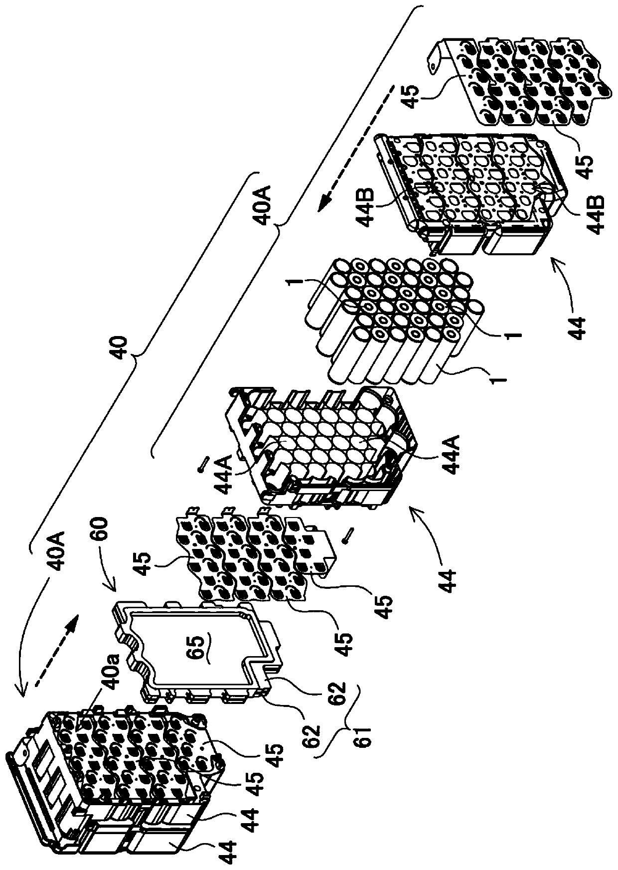
[0026] figure 1 sectional view of and figure 2 In the power supply device 100 shown in the enlarged cross-sectional view of , the circuit board 80 is arranged on the battery assembly 40 . battery assembly 40 such as image 3 As shown, a plurality of secondary battery cells 1 are arranged at fixed positions through a battery holder 44 . In the battery assembly 40 of the drawing, the secondary battery cells 1 are arranged in parallel in a horizontal posture and arranged in multiple stages and columns.

[0027] (circuit board 80)

[0028] The circuit board 80 is mounted with a control element 82 that implements a protection circuit for the secondary battery cells 1 of the battery assembly 40 . The protection circuit controls the current by detecting the voltage, remaining capacity, temperature, and current of the secondary battery cell 1 to prevent overcharging or overdischarging of the secondary battery cell 1. In addition, it also controls the secondary battery cell The e...


PUM


Abstract

The purpose of the present invention is to keep the temperature balance between a battery cell and a control element in an optimum range, and to prevent a deterioration of electric characteristics dueto a battery cell temperature increase and an operation failure due to a control element temperature increase. This power supply device includes a battery assembly (40) having battery cells (1) and acircuit substrate (80) on which a control element (82) for providing a protection circuit for the battery cells (1) is mounted, the circuit substrate (80) being fixed to a substrate holder (81). A bottom plate (81A) of the substrate holder (81) is disposed between the circuit substrate (80) and the battery assembly (40). The control element (82) is fixed to a surface of the circuit substrate (80)and is closely contacted with a potting resin (7). A heat insulating layer (83) is disposed between a back surface of the circuit substrate (80) and the bottom plate (81A).

Description

technical field [0001] The invention relates to a power supply device with built-in battery cells and electronic circuits. Background technique [0002] In a large-output and large-capacity power supply device, a plurality of battery cells are connected in series to increase the output voltage, and a plurality of battery cells are connected in parallel to increase the output current. This power supply device connects the protection circuit to the battery cell, and uses the protection circuit to control the charging and discharging current, thereby ensuring the aging and safety of the battery cell. The protection circuit of the battery cell is realized by the control element installed on the circuit board. In order to control the current of the battery cells, semiconductor switching elements such as FETs and transistors are installed on the circuit board as power elements for controlling the current. Since the power element controls a large current, a large current flows, a...

Claims


Application Information

Patent Timeline
IPC IPC(8): H01M10/658H01M2/10H01M10/613H02J7/00H01M50/209H01M50/227
CPCH01M10/613H01M10/658H02J7/00Y02E60/10H01M50/227H01M50/209
Inventor 米田晴彦拝野真己岸田裕司
Owner 松下新能源株式会社
Why Eureka
Try Eureka