Al technical title is built by PatSnap Al team. It summarizes the technical point description of the patent document.
A door sensor switch, fire door technology, applied in magnetic/electric field switches, electric switches, electrical components, etc., can solve the problems of fire door switch structure failure, non-use of door sensor switch, leakage of fixing screws, etc., to achieve anti-theft function Strong, strong installation versatility, precise alignment effect
Active Publication Date: 2020-05-15
临沂佳卫消防科技有限公司
View PDF6 Cites 0 Cited by
Summary
Abstract
Description
Claims
Application Information
AI Technical Summary
This helps you quickly interpret patents by identifying the three key elements:
Problems solved by technology
Method used
Benefits of technology
Problems solved by technology
Once the electromagnetic failure or electric connection failure occurs, the door magnetic switch will not be able to use, resulting in failure of the fire door switch structure
Moreover, the fixing screws of the existing door magnetic switch are often leaked, and the anti-theft effect is not good.
Method used
Image
Click on the blue label to locate the original text in one second.
Reading with bidirectional positioning of images and text.
Examples
Embodiment
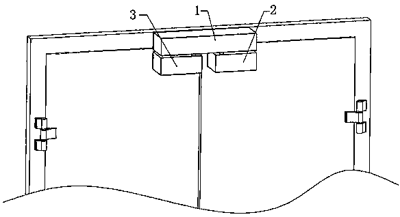
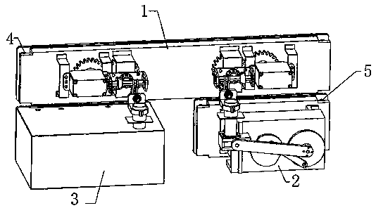
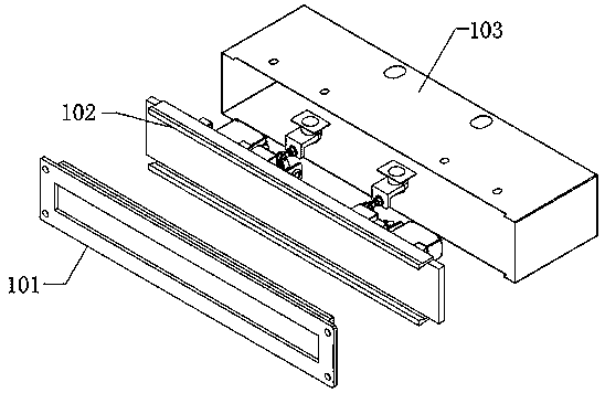
[0027] Example: such as figure 1 , figure 2 , image 3 , Figure 4 , Figure 5 , Figure 6 , Figure 7 , Figure 8 , Figure 9 , Figure 10 A door magnetic switch for a fireproof door is shown, including a door magnetic body assembly 1, a right door magnetic lock body assembly 2, a left door magnetic lock body assembly 3, a door magnetic main body screw 4, and a door magnetic lock body screw 5, wherein the door magnetic The main body assembly 1 includes: door magnetic main body base 101, door magnetic main body slide seat 102, door magnetic main body cover 103, fixed chute 104, main motor outer support 105, main motor inner support 106, main body driving motor 107, main main gear 108, main body transmission gear 109, transmission part support 110, transmission part U-shaped plate 111, connecting shaft 112, radial bevel gear 113, axial bevel gear 114, transmission hexagonal 115, locking block 116, transmission plate 117, transmission connection Rod 118, fixed pin 11...
PUM
Abstract
The invention discloses a fireproof door magnet switch. The fireproof door magnet switch comprises a door magnet body assembly, a right door magnet lock body assembly, a left door magnet lock body assembly, a body drive motor, a body main gear, a body transmission gear, a radial bevel gear, an axial bevel gear, a transmission hexagon, a transmission connecting rod, a lock catch, spring bolts, driving cams, driving cranks, driven cams, driven cranks, pushing sliding blocks, following wheels, lock body motors, gear supporting shafts, lock body main gears, gear locking screws, lock body driven gears and gear transmission shafts. The door magnet body assembly is fixed to a fireproof door frame. The right door magnet lock body assembly and the left door magnet lock body assembly are symmetrically fixed to a door leaf. In the left door magnet lock body assembly and the right door magnet lock body assembly, the lock body motors are used for driving matched transmission of gears and crank cammechanisms, the spring bolts fixed in the pushing sliding blocks are driven to move front and back to be matched with the lock catch in the door magnet body assembly fixed to the fireproof door frame,and door leaf locking, opening and closing are achieved.
Description
technical field [0001] The invention relates to an electromagnetic switch device, in particular to a magnetic switch for a fire door. Background technique [0002] The traditional fire door magnetic switch is mainly composed of a switch and a magnet. The magnet is encapsulated in the magnetic housing to generate a constant magnetic force. The normally open reed switch installed inside and the distance between the door leaf and the door frame , to realize the opening and closing of the fire door. Once the electromagnetic failure or electrical connection failure occurs, the door magnetic switch will be unusable, resulting in failure of the fire door switch structure. Moreover, many fixing screws of the existing door magnetic switch leak, and the anti-theft effect is not good. Contents of the invention [0003] Aiming at the above problems, the present invention provides a magnetic door switch for fire doors, which drives the front and rear movement of the lock tongue throu...
Claims
Application Information
Patent Timeline
Application Date:The date an application was filed.
Publication Date:The date a patent or application was officially published.
First Publication Date:The earliest publication date of a patent with the same application number.
Issue Date:Publication date of the patent grant document.
PCT Entry Date:The Entry date of PCT National Phase.
Estimated Expiry Date:The statutory expiry date of a patent right according to the Patent Law, and it is the longest term of protection that the patent right can achieve without the termination of the patent right due to other reasons(Term extension factor has been taken into account ).
Invalid Date:Actual expiry date is based on effective date or publication date of legal transaction data of invalid patent.