H-shaped steel beam and h-shaped steel column strong shaft assembled joint and construction method

An H-shaped steel and shaft assembly technology, which is applied in the direction of columns, pillars, pier columns, etc., can solve the problems of inconvenient on-site construction and installation of workers, stress concentration, etc., and achieve the effect of increasing connection stability, large node rigidity, and reducing installation steps

Active Publication Date: 2021-05-04
华川建设集团有限公司
View PDF5 Cites 0 Cited by
  • Summary
  • Abstract
  • Description
  • Claims
  • Application Information

AI Technical Summary

Problems solved by technology

[0004] The above-mentioned existing technical solutions have the following defects: in the process of using bolts to connect the steel column and the connecting plate, it is necessary to maintain the abutment of the opposite end faces of the steel column and the connecting plate and the alignment of the corresponding bolt installation holes and place the bolts at the same time , it is very inconvenient for the staff to construct and install on site; at the same time, there is serious stress concentration at the bolt connection between the end plate and the steel column, and the force perpendicular to the length direction of the steel beam is subjected to the corresponding shear force by the bolt , when the steel beam is under a large force, the bolts may be damaged and affect the stability of the beam and column connection

Method used


Image

  • H-shaped steel beam and h-shaped steel column strong shaft assembled joint and construction method
  • H-shaped steel beam and h-shaped steel column strong shaft assembled joint and construction method
  • H-shaped steel beam and h-shaped steel column strong shaft assembled joint and construction method

Examples


Embodiment Construction

[0038] The present invention will be described in further detail below in conjunction with the accompanying drawings.

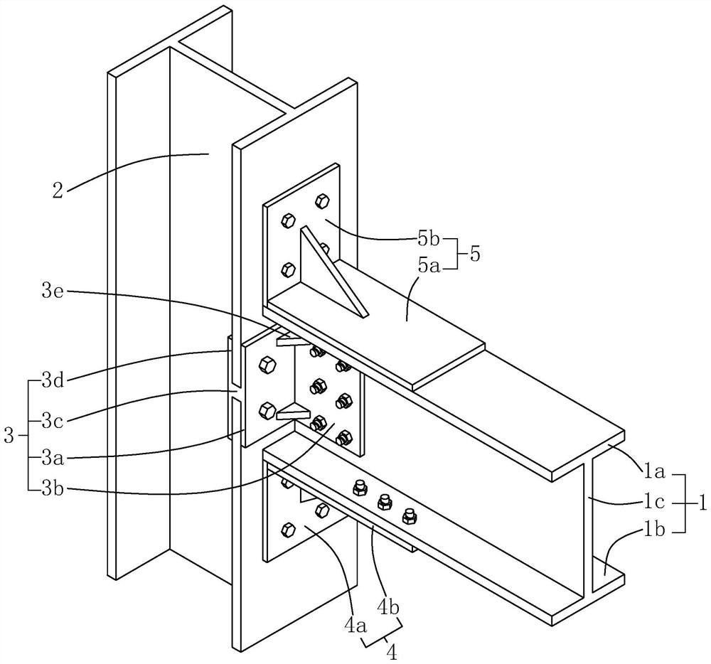
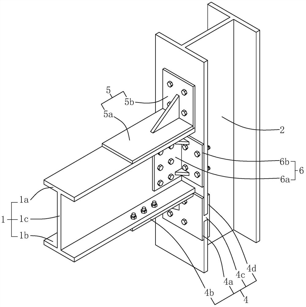
[0039] refer to figure 1 and figure 2 , which is an H-shaped steel beam and H-shaped steel column strong shaft assembled node disclosed in the present invention, including H-shaped steel beam 1, H-shaped steel column 2, first connecting piece 3, second connecting piece 4, and third connecting piece 5 and the fourth connector 6; wherein, the H-shaped steel beam 1 includes a horizontal upper flange 1a, a lower flange 1b and a vertical web 1c; the H-shaped steel column 2 is vertically arranged, and the H-shaped steel column A wing plate of 2 is used to connect with the H-shaped steel beam 1.

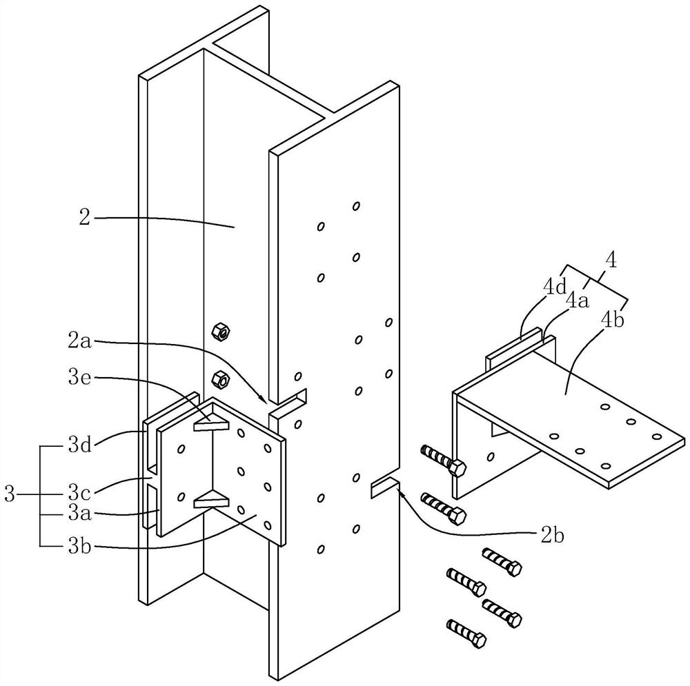
[0040] refer to figure 1 and image 3 , the first connecting piece 3 is installed on the wing plate of the H-shaped steel column 2, the first connecting piece 3 includes a first L-shaped plate, a first plug-in block 3c and a first limiting plate 3d, specifically, the ...


PUM


Abstract

The invention relates to an H-shaped steel beam and H-shaped steel column strong shaft assembled node and a construction method, including an H-shaped steel beam and an H-shaped steel column, and the H-shaped steel beam includes an upper flange, a lower flange and a web; the node It also includes a first connecting piece, a second connecting piece and a third connecting piece, the first connecting piece includes a first plate, a second plate and a first socket block; the first plate is connected with H-shaped steel stud bolts; the second plate is connected with The web plate is fixed by bolts; the first plug-in block is set on the first plate, and the H-shaped steel column flange is provided with a first plug-in slot; the second connector includes a first vertical plate, a first horizontal plate and a second plug-in block, The first vertical plate is connected to the H-shaped steel column by bolts; the first horizontal plate is connected to the lower wing by bolts; the second plug-in block is set on the first vertical plate, and the H-shaped steel column wing is provided with a second insertion groove; the third connection The piece is fixed on the upper wing plate, and the third connecting piece is connected with the H-shaped steel column bolt. This node is convenient for on-site construction and installation, and can reduce the shear force on the bolts, reducing the damage to the bolts and affecting the stability of the beam-column connection.

Description

technical field [0001] The invention relates to the technical field of building steel structure construction, in particular to an H-shaped steel beam and H-shaped steel column strong shaft assembled node and a construction method. Background technique [0002] As a representative of green buildings, steel structure has the characteristics of good material comprehensive performance, high material utilization rate and superior safety performance. In multi-story and high-rise steel structures, H-shaped steel beams and H-shaped steel columns are used as the main load-bearing components, and the nodes used to connect H-shaped steel beams and H-shaped steel columns are mainly used to transmit bending moments and The effect of shear force is the key to affect the mechanical properties of steel structure houses. [0003] At present, the most commonly used beam-to-column joints in prefabricated steel structure houses are bolted welded joints. The bolt-welded connection node is to w...

Claims


Application Information

Patent Timeline
Patent Type & Authority Patents(China)
IPC IPC(8): E04B1/24E04B1/58E04G21/00E04C3/32
CPCE04B1/2403E04B2001/2406E04C3/32E04G21/00
Inventor 魏庆贵魏熙龚甜张德炎
Owner 华川建设集团有限公司
Why Eureka
Try Eureka