Thermostat for controlling coolant flow path

A flow path, controlled cooling technology, applied in the control/regulation system, temperature control, engine cooling, etc., can solve the problems of low engine, power reduction, and insufficient combustion of the mixture, and achieve the effect of easy manufacture and simple structure

Active Publication Date: 2020-06-09
VOLVO CAR CORP
View PDF8 Cites 2 Cited by
  • Summary
  • Abstract
  • Description
  • Claims
  • Application Information

AI Technical Summary

Problems solved by technology

If the main valve of the thermostat is opened too late, it will cause the engine to overheat; if the main valve is opened too early, the engine temperature will be too low, and the engine warm-up time will be prolonged, resulting in insufficient combustion of the mixture, reduced power, increased Oil consumption, and cause poor lubrication, but also cause excessive emissions
[0003] Existing various forms of thermostats, their structures are usually more complicated, or the manufacturing process is more troublesome

Method used


Image

  • Thermostat for controlling coolant flow path
  • Thermostat for controlling coolant flow path
  • Thermostat for controlling coolant flow path

Examples


Embodiment Construction

[0023] The following figures describe some possible embodiments of the present application.

[0024] This application relates generally to thermostats in cooling systems. The cooling system is used for staged cooling of equipment. The device may be an engine or the like. Therefore, the following uses an engine as an example to describe the embodiment of the present application, but the present application can also be used for cooling other equipment.

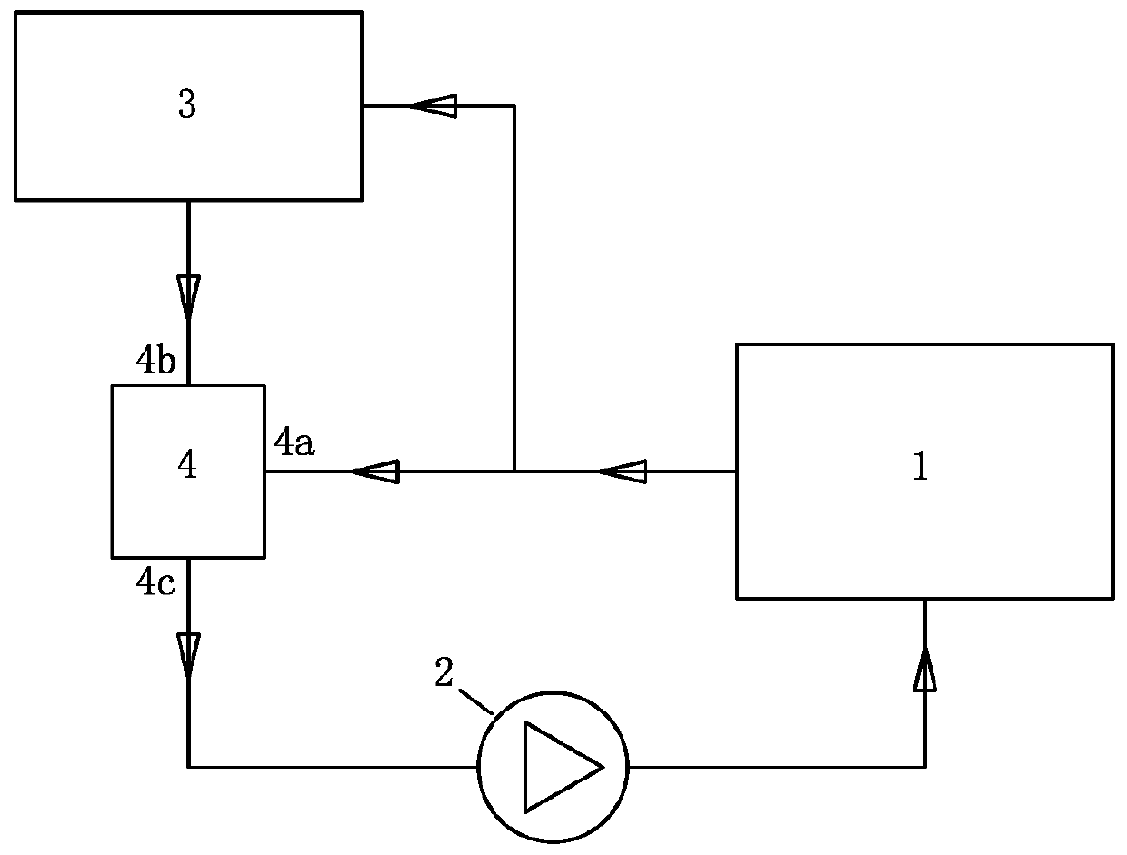
[0025] figure 1 A cooling system suitable for the application is shown for cooling the engine 1 . A pump 2 , a radiator 3 and a thermostat 4 are arranged in the coolant flow path of the cooling system. The pump 2 drives the coolant to flow in the coolant flow path, as indicated by the arrows. The thermostat 4 has a first inlet 4a on the engine side, a second inlet 4b and an outlet 4c on the radiator side. Both the first inlet 4a and the second inlet 4b of the thermostat 4 can be opened and closed, so that different operati...


PUM


Abstract

The invention discloses a thermostat for controlling a coolant flow path. The thermostat comprises a cavity assembly, a wax bag, a blocking bracket and a main valve block, wherein the cavity assemblydefines an inner cavity and a first inlet and a second inlet are configured to establish fluid communication between the inner cavity and the coolant flow path; the wax pack is disposed in the inner cavity and comprises a push rod fixed to the cavity assembly and a wax pack main body movable relative to the push rod; the blocking bracket is configured to be driven by the wax pack main body for opening and closing of the first inlet; and the main valve block is configured to be driven by the wax pack main body and/or the blocking bracket for opening and closing of the second inlet. The wax packmain body comprises a housing, a rubber tube and a gland, wherein the housing is filled with wax; a cylindrical body of the rubber tube is inserted into the housing; and the gland has a buckle part,and the buckle part is buckled onto the housing to seal the rubber tube between the housing and the gland. The thermostat is easy to manufacture and can achieve precise control.

Description

technical field [0001] The present application relates to a thermostat for controlling a coolant flow path, which is capable of controlling various coolant flow paths, especially an engine coolant flow path. Background technique [0002] In order to ensure the normal operation of the engine, it is necessary to control the operating temperature of the engine within an appropriate temperature range. Engines are usually equipped with a cooling system to control engine temperature. A radiator, for example a grille radiator, is arranged in the coolant flow path of the cooling system. The coolant that has warmed up after cooling the engine can flow through the radiator to cool the coolant down. When the engine temperature is still low, the coolant does not need to flow through the radiator, or only a part of the coolant needs to flow through the radiator. For this reason, a thermostat is usually installed in the coolant flow path. The purpose is to automatically adjust the amou...

Claims


Application Information

Patent Timeline
Patent Type & Authority Applications(China)
IPC IPC(8): F01P7/16
CPCF01P7/165F01P2007/146F01P7/16G05D23/022F01P11/04
Inventor 徐永萍曹雪翔
Owner VOLVO CAR CORP
Why Eureka
Try Eureka