Check patentability & draft patents in minutes with Patsnap Eureka AI!

Caster device

A technology of casters and wheel seats, which is applied in the direction of casters, wheels, transportation and packaging, etc. It can solve the problems of inconvenient use, inconformity with the user's operation habits, time-consuming braking or releasing the brakes, etc., and achieves simple and convenient operation. Effect

Active Publication Date: 2021-07-09
CATIS PACIFIC MFG CORP
View PDF11 Cites 0 Cited by
  • Summary
  • Abstract
  • Description
  • Claims
  • Application Information

AI Technical Summary

Problems solved by technology

This type of caster allows the user to control the movement of the platform, and when necessary, step on the brake pedal to limit the rotation of the caster, and when the platform needs to be moved again, it is usually designed to toggle the brake pedal in the opposite direction To release the restriction, using the foot to move the brake pedal in the opposite direction not only does not conform to the user's operating habits, but also often takes more time to try because you don't know whether the brake pedal is braking or releasing the brake when you step on it. Not convenient, there is still room for improvement

Method used


Image

  • Caster device
  • Caster device
  • Caster device

Examples


Embodiment Construction

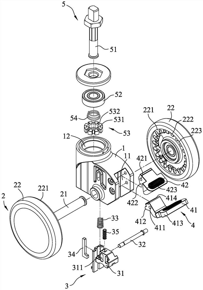
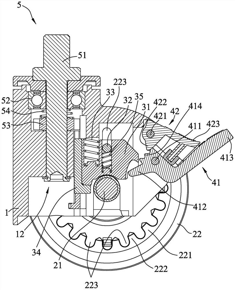
[0018] refer to figure 1 , 2 , an embodiment of the caster device of the present invention, the caster device includes a wheel base 1, a moving unit 2, a steering unit 5, a braking unit 3, and a driving unit 4.

[0019] The wheel base 1 defines an accommodating space 11 , and a shaft hole 12 extending upward and downward to the accommodating space 11 .

[0020] The mobile unit 2 includes a wheel shaft 21 passing through the wheel seat 1, and two rotating wheels 22 mounted on the left and right ends of the wheel shaft 21 and capable of rotating. Each wheel 22 includes a wheel facing the other wheel 22. On the inner surface 221 , at least one inner surface 221 is provided with a plurality of first tooth blocks 222 arranged at intervals around its own axis, and two adjacent first tooth blocks 222 jointly define a first tooth groove 223 .

[0021] The steering unit 5 is passed through the shaft hole 12, and includes a shaft 51 inserted in the shaft hole 12 and capable of rotatin...


PUM


Abstract

A caster device, comprising: a wheel base, a moving unit, a braking unit, and a driving unit; the moving unit is passed through the wheel base, and includes two rotatable runners, each of which has several The first tooth slots arranged at intervals; the brake unit includes a brake seat and a first brake lever, and the brake seat can move in the braking position and the active position relative to the wheel base. Compared with the active position, the first brake lever moves upward and is embedded in the corresponding first tooth groove; the drive unit includes a brake drive plate, and a brake release drive plate, which swings downward The brake drive plate can move the brake seat to the braking position, and the brake release drive plate can move the brake seat to the active position by swinging down. The operation is simple and more customary.

Description

technical field [0001] The invention relates to a caster, in particular to a caster device with a stop brake function. Background technique [0002] Generally, for the convenience of movement, several casters are usually installed under the loading platform. In order to prevent the carrier from moving on uneven ground, casters with brake pedals can be seen on the market. This type of caster allows the user to control the movement of the platform, and when necessary, step on the brake pedal to limit the rotation of the caster, and when the platform needs to be moved again, it is usually designed to toggle the brake pedal in the opposite direction To release the restriction, using the foot to move the brake pedal in the opposite direction not only does not conform to the user's operating habits, but also often takes more time to try because you don't know whether the brake pedal is braking or releasing the brake when you step on it. Not convenient, there is still room for im...

Claims


Application Information

Patent Timeline
Patent Type & Authority Patents(China)
IPC IPC(8): B60B33/00
CPCB60B33/0078
Inventor 林青松
Owner CATIS PACIFIC MFG CORP
Features
  • R&D
  • Intellectual Property
  • Life Sciences
  • Materials
  • Tech Scout
  • Unparalleled Data Quality
  • Higher Quality Content
  • 60% Fewer Hallucinations
Learn More