Automatic error compensation method for infrared thermal imaging temperature measurement system

A technology of infrared thermal imaging and automatic compensation, applied in radiation pyrometry, sensing the radiation of moving objects, measuring devices, etc., can solve the problem of target distance sensitivity and achieve zero investment, zero lag, and high cost performance

Active Publication Date: 2020-08-25
SHANGHAI JIAO TONG UNIV
View PDF11 Cites 5 Cited by
  • Summary
  • Abstract
  • Description
  • Claims
  • Application Information

AI Technical Summary

Problems solved by technology

[0008] In view of the defects in the prior art, the purpose of the present invention is to provide an automatic compensation method for distance and angle errors of the infrared thermal imaging temperature measurement system, to solve the problem that the existing thermal imaging temperature measurement system is sensitive to the target distance, and to improve the temperature measurement accuracy

Method used


Image

  • Automatic error compensation method for infrared thermal imaging temperature measurement system
  • Automatic error compensation method for infrared thermal imaging temperature measurement system
  • Automatic error compensation method for infrared thermal imaging temperature measurement system

Examples


Embodiment Construction

[0035] The present invention will be described in detail below in conjunction with specific embodiments. The following examples will help those skilled in the art to further understand the present invention, but do not limit the present invention in any form. It should be noted that those skilled in the art can make several modifications and improvements without departing from the concept of the present invention. These all belong to the protection scope of the present invention.

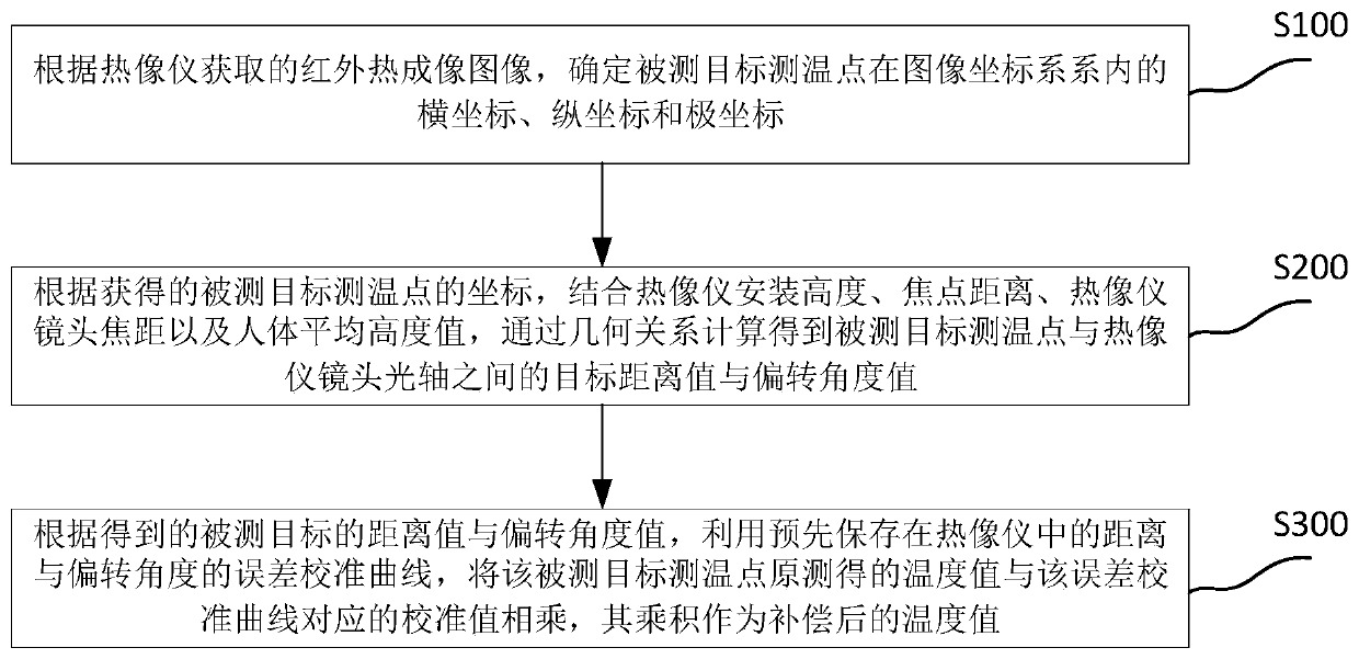
[0036] figure 1 It is a flow chart of the automatic error compensation method in an embodiment of the present invention.

[0037] refer to figure 1 As shown, the distance and angle error automatic compensation method of the infrared thermal imaging temperature measurement system in this embodiment includes:

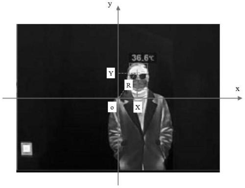
[0038] S100, according to the infrared thermal imaging image acquired by the thermal imager, determine the abscissa, ordinate and polar coordinate of the temperature measurement point of the ...


PUM


Abstract

The invention provides a distance and angle error automatic compensation method for a thermal imaging temperature measurement system, and the method comprises the steps: determining the abscissa, ordinate and polar coordinate of a measured target temperature measurement point in an image coordinate system according to an infrared thermal imaging image obtained by a thermal imager; combining the thermal imager installation height, the focus distance, the thermal imager lens focal length and the human body average height value, and calculating the distance value and the deflection angle value ofthe measured target through the geometrical relationship; and multiplying the originally measured temperature value by the corresponding calibration value by using a distance error calibration curvepre-stored in the thermal imager to obtain a product which is a compensated temperature value. The distance and angle error compensation method provided by the invention does not need to additionallyadd any hardware equipment, does not need additional acquisition action, can automatically adapt to the distance and deflection angle change of the measured target, has zero investment and zero lag, has extremely high cost performance, and has wider practicability and universality.

Description

technical field [0001] The invention relates to an error compensation method of an infrared thermal imaging temperature measurement system, in particular to an automatic compensation method for distance and / or angle errors of an infrared thermal imaging temperature measurement system. Background technique [0002] The advantages of the infrared thermal imaging body temperature testing system are obvious: long-distance, non-contact, multi-target, suitable for airports, subways, railways and building entrances, etc. The significance of body temperature testing lies in early screening, which is mainly used to find people with suspected fever in the crowd, and further conduct accurate body temperature measurement and follow-up inspection. [0003] However, the current thermal imaging body temperature screening system still has serious deficiencies, especially due to the influence of various factors in the use process, resulting in a significant drop in temperature measurement ac...

Claims


Application Information

Patent Timeline
Patent Type & Authority Applications(China)
IPC IPC(8): G01J5/00G01J5/52
CPCG01J5/0025G01J5/53G01J5/80
Inventor 赵辉陶卫吕娜陈启恒付堉家
Owner SHANGHAI JIAO TONG UNIV
Why Eureka
Try Eureka